- First Make/Last Break
A connector product where certain positions are designed to engage first and disengage last. This is used for applications where the order of engagement is critical, such as types where the ground connection must be established first and released last to prevent damage to the system.
- Operating Travel Range
25% - 100% of a spring-loaded pin’s maximum stroke capability. This is the range of compression a spring-loaded contact may operate in. There are some products that may fall outside this range due to specific design characteristics. Note that at compression less than mid stroke the electrical and mechanical performance may not meet the stated specifications. Using spring-loaded contacts at maximum stroke there is a risk of over compression due to tolerance variation which may lead to damage of spring-loaded components and reduced mechanical life.
- Wrapost
A termination style on PCB pins and connectors featuring a post with a square cross section, intended for making electrical connections via wire wrapping. This is a process in which a wire is wrapped around the post to form a gas-tight electrical connection without soldering (when proper tooling is used). Wire wrapping allows for fast repairs as the connection can be removed quickly and easily without damaging the terminal. Mill-Max offers wrapost termination features for a variety of discrete and connector products, often including different length options and # of wraps (commonly 1-3). View Examples
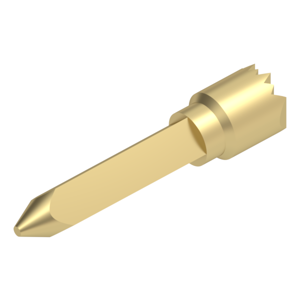
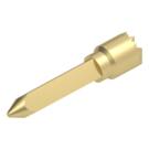
- Through-Hole Mount (TH)
A termination style provided on both discrete and connector products where a machined tail or post on the bottom of the component is soldered into a mounting hole on a PCB. This termination style is preferred over SMT products in applications where the component may be subjected to lateral loads, since the rigid tail helps anchor the part to the PCB. Mill-Max currently offers through hole termination features in varying lengths and diameters, with options for both vertical and horizontal mounting.
- Stub Tail
A termination method provided on select DIP, SIP and PGA style sockets. This mounting style is comparable to most standard SMT designs, with the chief exception being the floating nature of the receptacles within the insulator. The added range of movement acts as a buffer and helps compensate for unevenly screened solder paste during assembly. View Examples
- High Temperature
Parts designed to withstand higher temperatures than what is specified for the standard lineup. This often involves replacing a material in the part/assembly with an alternative that is better suited to withstand stress relaxation due to heat. Mill-Max currently offers a line of high temperature receptacle products which use a contact clip fabricated out of beryllium nickel as opposed to beryllium copper; which are rated for “down-hole” and “burn-in” applications up to 300°C. In spring-loaded applications, Mill-Max offers higher temperature options in the form spring pins constructed with stainless steel springs.
- Z-bend
A feature provided on select SIP connectors where two bends are formed into the solder tails of through-hole interconnect components, allowing them to be horizontally surface mounted to the board. This termination method is useful for applications where a horizontal/parallel connection must be made, but the PCB cannot tolerate a right angle through hole component. View Examples
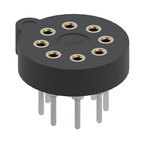
- Transistor Socket (TO)
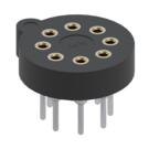
Circular sockets designed to make the insertion/extraction of transistors and diodes easy and convenient, especially in the field. This is achieved by making the device pluggable with a reliable mechanical and electrical connection to the mated transistor lead. The diameters and spacings are pre-determined to meet most standard package types, namely adhering TO-5 and TO-100 footprint requirements. Offered in both through hole and surface mount termination options. View Examples
- Tin Whisker Growth
A phenomenon that occurs where small metal hairs grow between soldered joints and/or components, forming mini electrical paths which can lead to short circuits. They pose a serious problem for electronics of all types since they can grow spontaneously, are almost invisible to the naked eye, and can bridge fairly large distances. Whisker growth is most often mitigated by using a combination of tin (Sn) and lead (Pb) where the minimum lead content is 3%. For RoHS compliant applications, specifying a matte finish as opposed to bright finish will also aid in mitigation.
- Dual Inline Package (DIP)
An interconnect component that consists of a rectangular insulator with two parallel rows populated with either male pins or female receptacles. These products are designed to mate with equivalently spaced electronic packaging components or designed to generate a comparable footprint to these products on a PCB. Commonly specified with pitch/pin-to-pin spacing of .100”, .070” pitch spacing options are offered for shrink DIP package applications. The parallel rows are offered in more varied spacing options, typically ranging from .200” to .900”. Offered in a variety of termination styles including solder tail, SMT, wire termination, and press-fit options. View Examples