Solder Cup Contact and Connector Applications
 Mill-Max solder-cup products deliver precision, reliability, and ease of use. Available across a broad range of male terminals, receptacles, spring-loaded pins, and connector arrays, these components are engineered for clean, secure wire termination. The open-cup design holds the wire firmly in place during soldering, while the cut-away shape ensures excellent access for soldering irons—no matter the technique—resulting in consistent, high-quality solder joints. With clear visibility for inspection and effortless handling, Mill-Max solder-cup solutions help streamline assembly and enhance connection integrity across a wide range of applications. Mill-Max solder-cup interconnects deliver versatility, precision, and performance across a wide range of applications. Supporting wire sizes from 32 AWG to 14 AWG, our lineup includes receptacles for mating pins from .015” (0,38 mm) to .082” (2,08 mm), male terminals with pin diameters from .016" (0,41 mm) to .078” (1,98 mm), and spring-loaded pins offering strokes from .055” (1,40 mm) to .090” (2,30 mm). Choose from vertical mount connectors in single and double row formats or space-saving right-angle options in single row. Uniformly aligned solder cups ensure efficient, consistent soldering, while recent innovations—especially in right-angle versions—feature enhanced design elements that prevent pin rotation during assembly. Whether you're optimizing for board space or ensuring a reliable electrical connection, Mill-Max delivers robust solutions built for performance and process efficiency. |
Solder-Cup Contact and Connector Applications SolutionsSolder-Cup Receptacles |
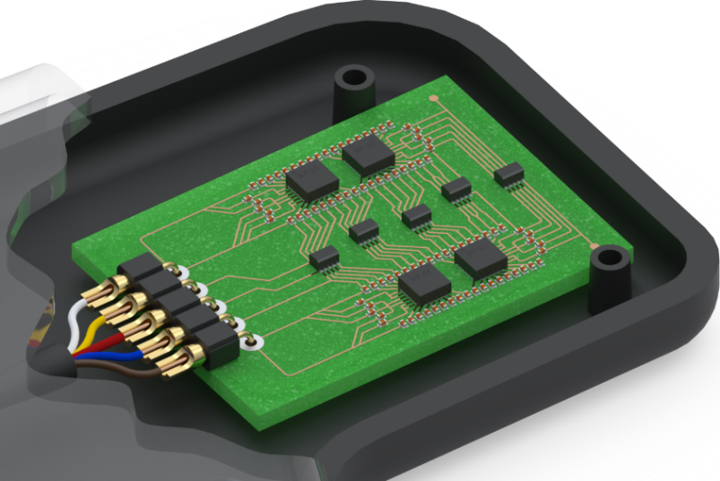
 Mill-Max solder-cup receptacles combine proven contact reliability with easy, secure wire termination. Featuring our high-performance contact clip technology, these receptacles ensure consistent engagement with pins or leads—even after repeated cycles. The integrated solder-cup simplifies wire attachment, enabling clean, durable solder joints for dependable connections in demanding applications. Solder-cup receptacles offer a simple, pluggable solution for connecting wired components to PCBs or cables. Ideal as female contacts in cable connectors, they are available in a wide range of sizes to accommodate various wire gauges and pin diameters—perfect for custom cable assemblies and compact electronic designs. |
Solder-Cup Terminal Pins |
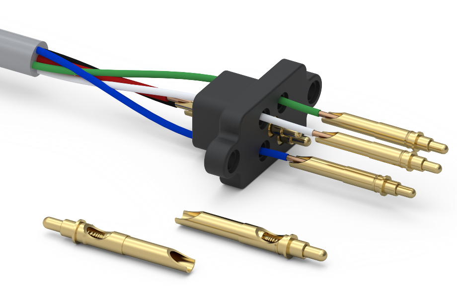
 Mill-Max precision-machined brass terminal pins with solder-cup features turn wires into high-performance interconnect solutions. Ideal for creating reliable, pluggable connections, solder-cup terminals pair easily with receptacles or connectors to link wires, cables, or PCBs. In wire-to-board applications, they offer a cleaner, more durable alternative to direct-to-board soldering—especially when working with delicate, fine-gauge wires. When combined with solder-cup receptacles, they form a robust, high-quality foundation for custom cable assemblies and connector designs. |
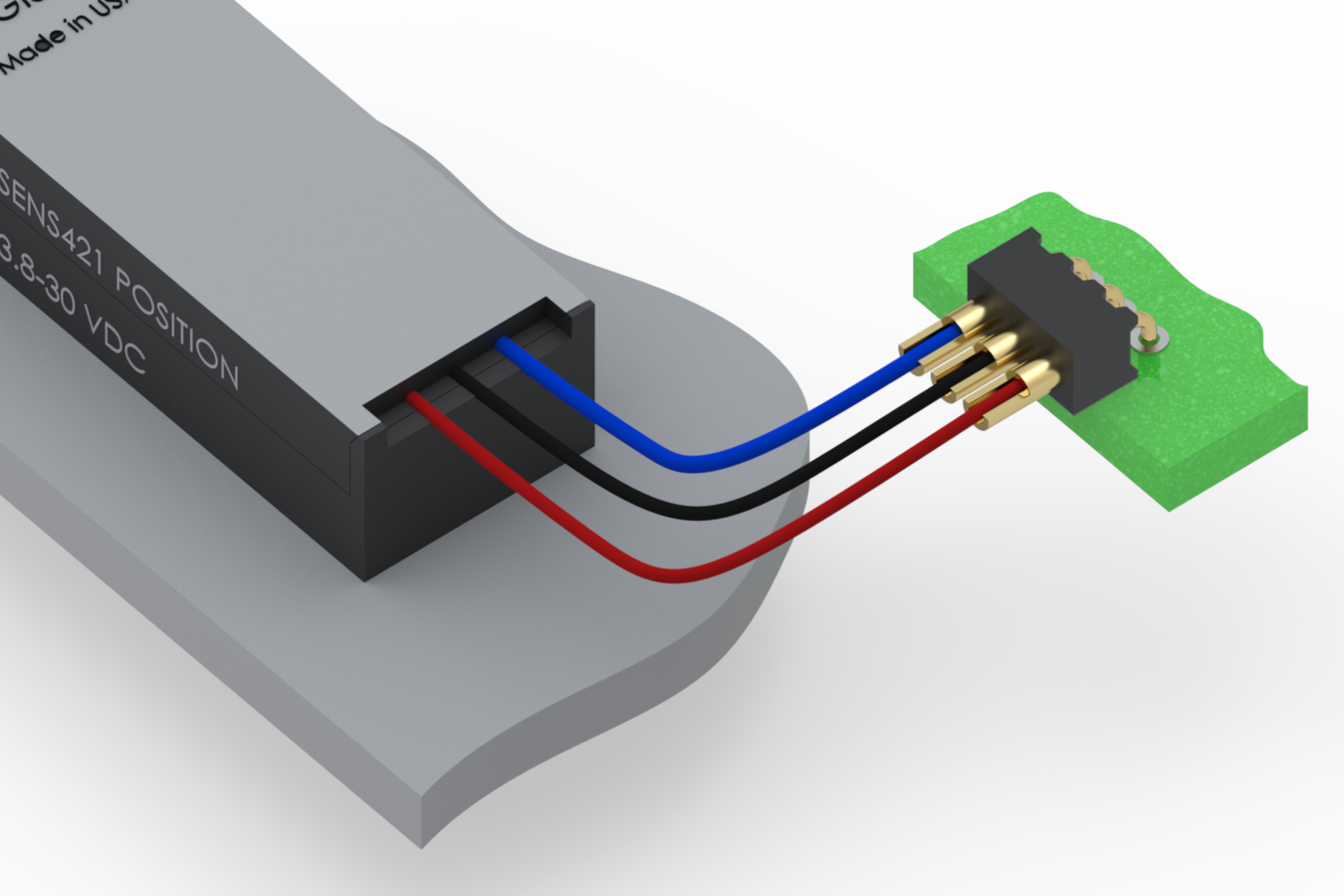
Spring-Loaded Contacts with Solder-Cups |
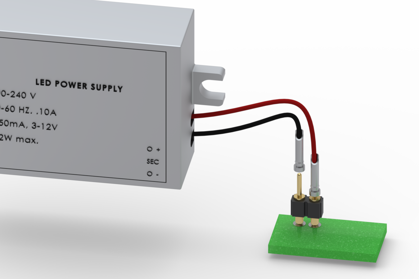
 Mill-Max spring-loaded pins and connectors, provide a highly-reliable, precision made interconnect solution ideal for a number of demanding application requirements. Spring-Loaded pins with an integrated solder-cup offer a unique combination of interconnect options, such as battery leads soldered to spring pins mounted in a docking/charging station. The spring-loaded pin with solder-cup feature enables efficient attachment of wires while the spring-loaded plunger is the proper interface for mating to devices with pads or lands. Several of the spring-loaded pins include a press-fit feature for convenient mounting in assembly housings or boards. In the example shown here, the 0973 spring-loaded pins are used in a cable assembly as part of a quick-connect system. In this application the wires are passed through the housing where they are soldered to the cups. The wires and pins are pulled back through the housing until the press-fit feature is engaged, then, pushing on the shoulders of the pins, they are secured into the housing. The spring pins are designed with the location of the shoulder and barb press-fit feature to ensure the pins will not be pulled from the insulator due to strain on the wires. |
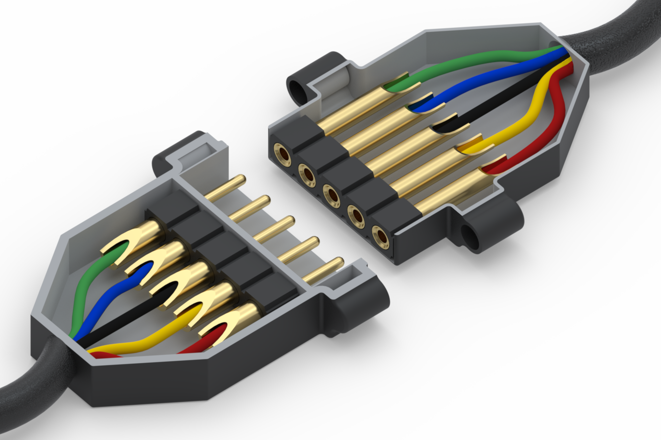
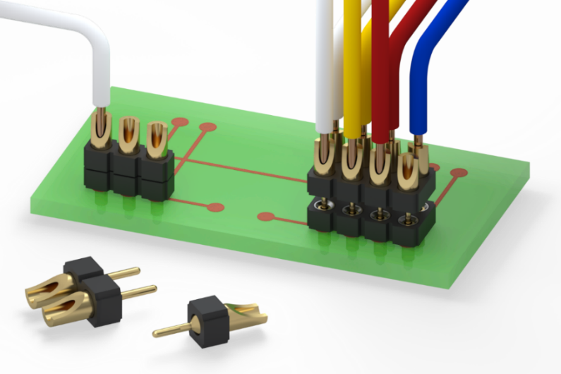
.100" (2,54 MM) Pitch Solder-Cup Pin & Socket Interconnects |
| Mill-Max .100” (2,54mm) pitch solder-cup connectors offer versatile, high-reliability solutions for robust wire termination. Available in low-profile, right-angle, and high-current versions, PCB socket interconnects feature uniformly aligned solder cups for efficient assembly and are offered in single or double row formats. Their durable design supports heavier gauge wires—up to 22 AWG for standard versions and up to 20 AWG for high-current styles. Male pins range from .020” to .030” in diameter, with matching receptacles accepting .015”–.037”, making them ideal for demanding environments and rugged applications. |
 |
 |
 |
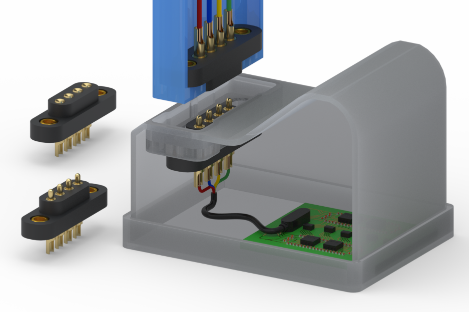
Fine Pitch Solder-Cup Pin & Socket Interconnects |
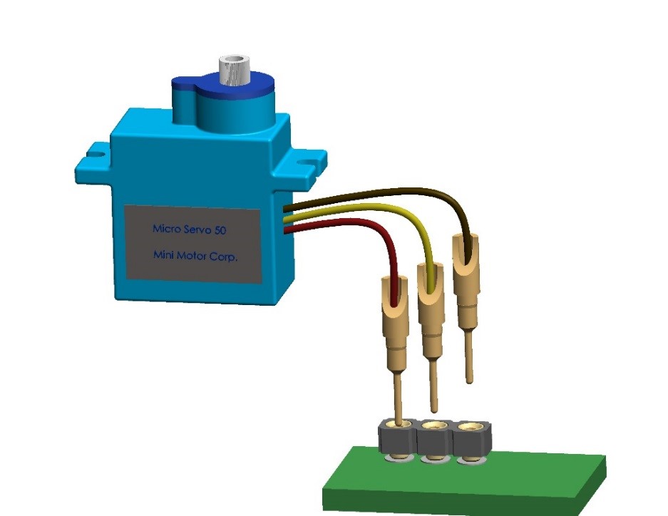
 Mill-Max fine-pitch solder-cup connectors deliver high-quality wire termination in compact, space-saving formats. Available on .050” (1,27mm) pitch and .079" (2mm) pitch, these connectors feature high-temperature insulators and precision-machined contacts for reliable performance in dense electronic designs. Engineered for uniform cup alignment, they simplify wiring with fine-gauge wires and miniature components. Compatible headers and sockets can be mixed and matched to meet a variety of interconnect needs. In the example shown, a sensor connects to a PCB in a parallel orientation using intrusive reflow soldering. Wires are then soldered to the terminals—often with lower-temperature solder—to protect board-level connections, ensuring a robust, dual-ended assembly. |
Spring-Loaded Headers and Target Connectors with Solder-Cups |
 Mill-Max spring-loaded connectors with solder-cup termination deliver reliable performance for power, charging, and quick-connect applications. Available on .050” (1,27mm), .100” (2,54 mm) and .1575” (4mm) pitch, these high-temperature assemblies feature precision spring pins and mating targets in rugged, vertical-mount styles—including extended travel and high-power variants. Ideal for battery docking stations and blind-mate systems, they ensure consistent, pluggable connections. To protect spring integrity during soldering, careful control of dwell time is essential—especially when using high-temp, lead-free solder. Beryllium copper and stainless steel springs withstand short-term temps of 205˚C (401˚F) and 260˚C (500˚F), respectively. All connectors include uniformly aligned cups for efficient soldering and are available in single and double row configurations. |
For additional help on how to correctly solder these type of terminals watch this video, Basic Soldering For Electronics Lesson 3 - "Cup Terminals", produced by PACE, Inc,
|
Need technical help or looking for a custom design? Contact us or review our custom capabilities.