The Contact Clip, the Heart of the Mill-Max Receptacle
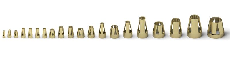
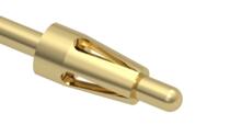
Inside every Mill-Max receptacle is a contact clip. A contact clip is a conductive, multi-finger, progressive die stamping designed to engage with a range of mating pins to form a reliable electrical connection. The ability for the contact to accommodate different size mating leads and apply force to them is due to the superior spring characteristics of beryllium copper and beryllium nickel. The contact fingers, also referred to as tines, are the stamped beams which open, envelop and apply force to the mated pin. The finger tips are typically coined to maximize the surface area in contact with the mated pin. These fingers allow the contact clip to engage, score and apply holding force to the mated pin, forming an electrical and gas tight connection at 3, 4 or 6 points of contact, depending on the selected contact.
Mill-Max currently offers 40 styles of contacts. This extensive family of contacts will accept round pins ranging from .008" to .102" diameter, as well as rectangular component leads and square wraposts, where the effective diameter is taken as the diagonal dimension of the lead. Receptacles with contact clips inserted in them are capable of 1,000 minimum insertion/extraction cycles for a broad range of applications. Mating pin size, shape and finish, along with application specific variables, will affect the life of a contact.
Many contacts are interchangeable within a given receptacle shell, provided the contacts have the same group designation. Standard receptacles found in the catalog and on the website can be easily assembled with alternate contacts to suit special applications, for example: low insertion force or high operating temperature. A convenient contact selector chart has been organized by alternate contact groupings to help assist you in choosing the right contact for your application.
| Contact Group | Contact Number | Accepts Minimum Pin Diameter (Inches) | Accepts Maximum Pin Diameter (Inches) | Contact Compliancy | Contact Length (Inches) | Number of Fingers | Contact Material* | Current Rating (For 30°C )** |
|---|---|---|---|---|---|---|---|---|
| None | 04 | .008 | .013 | .003 | .053 | 3 | BeCu | 5 Amps |
| None | 10 | .012 | .017 | .002 | .060 | 6 | BeCu | 6 Amps |
| A | 09 | .015 | .018 | .002 | .051 | 3 | BeCu | 9 Amps |
| A | 11 | .015 | .020 | .003 | .075 | 3 | BeCu | 8 Amps |
| A | 21 | .015 | .022 | .004 | .075 | 3 | BeCu | 6 Amps |
| A | 31† | .018 | .023 | .004 | .062 | 4 | BeCu | 13 Amps |
| A | 05 | .015 | .022 | .004 | .075 | 3 | BeCu | 7 Amps |
| A | 25 | .015 | .020 | .003 | .075 | 3 | BeNi | 12 Amps |
| B *** | 12 | .015 | .022 | .003 | .062 | 4 | BeCu | 11 Amps |
| B *** | 22 | .015 | .022 | .005 | .062 | 6 | BeCu | 10 Amps |
| C *** | 30 | .015 | .025 | .005 | .083 | 4 | BeCu | 12 Amps |
| C *** | 38 | .015 | .025 | .004 | .083 | 4 | BeNi | 12 Amps |
| C *** | 32 | .015 | .026 | .009 | .083 | 6 | BeCu | 8 Amps |
| C *** | 35 | .015 | .026 | .008 | .083 | 6 | BeCu | 8 Amps |
| C *** | 43 | .015 | .026 | .008 | .083 | 6 | BeCu | 8 Amps |
| K | 15 | .020 | .032 | .005 | .084 | 6 | BeCu | 12 Amps |
| K | 19 | .020 | .032 | .003 | .084 | 6 | BeCu | 12 Amps |
| D | 06 | .022 | .032 | .007 | .113 | 4 | BeCu | 16 Amps |
| D | 26 | .022 | .032 | .005 | .113 | 4 | BeNi | 16 Amps |
| D | 16 | .022 | .034 | .006 | .083 | 6 | BeCu | 16 Amps |
| D | 47 | .025 | .037 | .011 | .083 | 6 | BeCu | 15 Amps |
| D | 56 | .025 | .037 | .009 | .083 | 6 | BeNi | 14 Amps |
| L | 18 | .037 | .043 | .004 | .064 | 6 | BeCu | 12 Amps |
| L | 58 | .037 | .043 | .003 | .064 | 6 | BeNi | 12 Amps |
| E | 36 | .022 | .042 | .022 | .120 | 4 | BeCu | 16 Amps |
| E | 34 | .032 | .046 | .010 | .120 | 4 | BeCu | 17 Amps |
| E | 49 | .032 | .046 | .006 | .125 | 4 | BeCu | 8 Amps |
| E | 24 | .032 | .046 | .009 | .120 | 4 | BeNi | 16 Amps |
| F | 02 | .040 | .050 | .006 | .088 | 6 | BeCu | 16 Amps |
| F | 28 | .042 | .052 | .005 | .088 | 6 | BeCu | 8 Amps |
| J | 42 | .059 | .063 | .004 | .150 | 4 | BeCu | 24 Amps |
| J | 03 | .040 | .060 | .010 | .150 | 4 | BeCu | 18 Amps |
| G | 23 | .045 | .065 | .008 | .100 | 6 | BeCu | 18 Amps |
| G | 13 | .048 | .064 | .010 | .127 | 4 | BeCu | 19 Amps |
| G | 33 | .048 | .064 | .008 | .127 | 4 | BeNi | 19 Amps |
| H | 07 | .065 | .082 | .013 | .150 | 4 | BeCu | 26 Amps |
| H | 27 | .065 | .082 | .012 | .150 | 4 | BeNi | 30 Amps |
| H | 14 | .065 | .085 | .014 | .150 | 4 | BeCu | 27 Amps |
| None | 08 | .084 | .102 | .011 | .122 | 6 | BeCu | 30 Amps |
| None | 48 | .037 | .043 | TBD | .092 | 4 | BeCu | 25 Amps |
*The standard material of contact clips is beryllium copper 172 which is suitable for applications operating in a constant temperature environment under 150° C. For applications operating in a temperature over 150° C we offer select clips in beryllium nickel. Both materials are heat treated to achieve optimal spring characteristics & durability.
**The current rating of a contact clip is a function of its material thickness and pin engagement surface area. Note, this current rating (for a 10° C temperature rise above ambient) is conservative since it rates an individual pin/receptacle pair in the free air. For all practical applications, the current rating will be higher because of the heat sinking ability of wires and circuit traces attached to the pin and receptacles and will depend on the specific application.
*** Group B and C contacts may be interchanged. However, receptacle shell hole depth must be considered when replacing a group B contact with a group C as the group C contacts are longer. Contact an Application Engineer to determine if the exchange will work.
†The #31 contact clip cannot be assembled into all group A receptacle shells. Contact an Application Engineer for further assistance.
For more information on contact range, and proper design of pin length and diameter, read on for more.