Introduction to Maxnetic® Magnetic Connectors
What are Maxnetic® Connectors
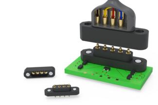
Maxnetic® connectors deliver the best of both worlds: magnetic alignment for intuitive, zero-force engagement and spring-loaded contacts for durable, high-reliability electrical connections.
The polarized neodymium magnets guide the mating halves into position, ensuring precise alignment even in blind or constrained conditions. Once mated, spring-loaded pins provide consistent contact force and superior conductivity across thousands of cycles.
This dual-action design reduces mechanical wear, simplifies user interaction, and ensures a secure, repeatable connection — making it ideal for rugged, high-use applications in medical, industrial, and military environments. This engineering notebook takes a tour of the major considerations when employing magnetic-and-spring-loaded connections inside high-performance electronic designs.
Advantages of Magnetic Connectors in Electronic Design
Maxnetic® connectors are engineered for zero-force magnetic mating, allowing users to establish a secure electrical connection without applying pressure. This stress-free engagement is particularly useful in tight spaces, wear-sensitive assemblies, or applications requiring frequent connections and disconnections.
Blind Mating
The connectors self-align using polarized neodymium magnets combined with mechanical body features. This ensures reliable mating even in blind or awkward orientations — minimizing user error and reducing connection time in field or production environments.
Durability
Built for high durability, these connectors are rated for up to one million mating cycles without degradation in electrical performance. That resilience is backed by precision-machined construction from Mill-Max to ensure mechanical integrity and consistent contact force over time.
Compactness
Despite their robustness, Maxnetic® connectors maintain a low-profile stack height — as low as 10.9 mm — making them a compact solution for space-constrained designs. Each contact is capable of handling up to 5.2 A*, delivering strong performance for power and signal applications alike.
Design Flexibility
Engineers can choose from multiple configurations including single- and double-row options, with both solder tail and solder cup terminations available to match a variety of assembly requirements.
*Current rating based on individual pin in free air. Actual performance may vary by configuration.
View Maxnetic® Connectors Configurations
Need technical help or looking for a custom design? Contact us or review our custom capabilities.
Contact Us See Custom Capabilities