Spring-Loaded General Applications
The Mill-Max spring-loaded pin is designed to last. High quality, precision machined, gold plated components provide for a highly reliable and robust interconnect product. Tested to a minimum of 50G shock and 10G vibration the Mill-Max spring-loaded pogo pin is built to withstand very harsh environments. Shock and vibration is per IEC 60512-6 & 60068-2 with acceptance criteria of no contact interruption > 1 microsecond and > 1.15 volts with .5 amps applied. The spring-loaded pins are compressed to mid-stroke (50% of maximum stroke capability) during the testing. However, as in any connector design it is important to understand that there are limitations inherent to the product.
| When designing in a Mill-Max spring-loaded pin, it is always best to aim to operate at the rated travel (mid-stroke) for optimal electrical and mechanical performance. Operating at less than mid-stroke may reduce electrical performance depending on the specifics of the application. Operating near full compression may reduce mechanical cycle life, although in certain “one-time compression” applications, working near the maximum stroke force may achieve favorable results. All electrical and mechanical ratings are based on mid-stroke compression. |  |
As a rule spring-loaded pins are designed to be used with force applied axially to the piston/plunger. Lateral engagement or side-loading of the piston should be avoided since this may cause damage to the piston or spring pin body by bending or fracturing it. For lateral engagement applications, consider using a solution from our Omniball® series, designed specifically for side-load applications.

In some designs it may be suitable to incorporate stand-off hardware or features to provide mechanical support in an effort to avoid over-compression of the spring pin.
Spring-Loaded Pin Mating Surface
The spring-loaded pin is very versatile and can be used to mate with a number of different surfaces. The only connection required in a spring pin application is for the plunger (or piston) to make contact to a flat or concave, plated surface. This flexibility in design can effectively eliminate one side of the traditional ‘pin and socket’ connector system. This can lead to cost saving and also a reduction in production time and process management during manufacturing.
Mill-Max Spring-Loaded Connectors can mate to any of the following surfaces:
- A conductive input/output pad found on the device/instrument to which it is mating.
- A gold plated land on a circuit board
- A gold plated nail head pin which can be soldered into the mating circuit board to act as a target. This can be a good choice when looking for a through-hole target solution there are a number of available options.
- Dedicated Mill-Max target pins which provide a large diameter, gold plated electrical path to the board. Available with flat or concave face options and through hole, SMT or wire termination styles. They are offered as individual pins or connectors.
- Dedicated Mill-Max target discs which provide a low profile large diameter, gold plated circuit path to the board. Useful for applications where vertical space is limited and SMT technology must be utilized.
- Target connectors which consist of arrays of target pins offered in a variety of styles and are often used to address applications requiring a conductive extension from the surface of one board or module to another

In some situations, production volumes of PC boards may have been assembled with a given spring-loaded pin, but field failures may indicate an insufficient amount of plunger compression is causing some intermittence issues. As board re-work and re-purchasing of longer spring pins is a costly venture, there is another, very cost-effective approach to solving this issue. Using a Target disc on the mating PC board will ensure that plunger compression is optimum for the application. If a custom solution must be sought, it can be more cost effective to modify the target side of the connection instead of the spring-loaded contact.
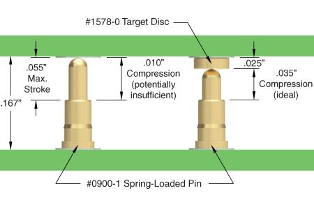
In the example cited above, the Mill-Max 0900-1 spring-loaded pin is employed. Since the goal is to compress the spring-loaded pin to at least mid-stroke (.0275”), the .010” compression is not acceptable. By introducing the 1578-0 Target pin on the mating PC board, an added .025” of plunger compression ensures an optimum amount of stroke at .035”.
For more specific application notes, use our product finder to narrow your search and review the application notes on the product detail page.
Spring-Loaded Board Assembly Considerations
For applications using SMT versions of Mill-Max spring-loaded connectors in an assembly, it is recommended to specify a round pad aperture .010" greater than the base diameter of the spring pin, to ensure a proper solder fillet. Most applications will require screening a solder paste thickness of .005-.006" thick and utilizing a SAC alloy solder paste to inhibit gold embrittlement. For pattern alignment of large SMT Mill-Max SLC footprints, alignment pins can be integrated into the insulator or on selected pins. | 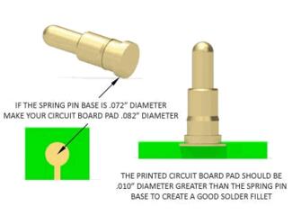 |
Mill-Max SMT Spring-Loaded Connectors in SIP and STRIP packages meet a co-planarity specification of .005" or less for connectors up to one inch long. The co-planarity, measured as the height of the pin bases relative to each other, is a critical factor in successfully soldering the connector to the PCB. For connectors longer than one inch the co-planarity may increase and should be determined through consultation with a Mill-Max applications engineer.
 | For soldering individual spring-loaded pins with solder-tails, a minimum plated through hole size of .004" greater than the spring pin tail diameter is recommended to promote capillary action of the solder. For soldering spring-loaded connectors with solder tails, a minimum plated through hole size of .008" greater than the spring pin tail diameter is recommended. Note: Hole and pad size recommendations are based on nominal feature dimensions of Mill-Max pins. They are presented here to provide guidance; they are not rules. Designers may choose to modify these recommendations to suit their applications. |
Need technical help or looking for a custom design? Contact us or review our custom capabilities.
Contact Us See Custom Capabilities