
Features of Organic Fibre Plug® Pass Through Interconnects
Series 834 and 835 are Mill-Max Organic Fibre Plug® receptacles assembled into a high temp thermoplastic insulator on a .100” (2,540mm) pitch, 834 in single row and 835 in double row. Every property of the receptacle carries over: the open bottom, the precision machined brass housing, the beryllium copper multi-finger contact and the solder barrier.
Mill-Max Series 834/835 Pass Through Sockets have a low .130" (3,3mm) profile and will accept .030" (0,76mm) diameter round pin, as well as industry standard .025" (0,64mm) square pin headers. Each receptacle has a current rating of 4.5 amps.
The open-bottom, through hole receptacle design makes it ideal for PCB-to-PCB stacking applications. In fact, the long, open bottom receptacle tail not only allows for conventional, top PCB mounting, but it can also be inverted and mounted below the PCB to create unique bottom-pin entry connectors. A bottom-entry connector is perfect for module stacking applications where a male pin header located on the base PCB must pass through a piggy backed board above it.
- Pass Through Sockets have a low .130” (3,3mm) profile and will accept .030” (0,76mm) diameter round pin, as well as industry standard .025” (0,64mm) square pin headers.
- Organic Fibre Plug® barriers prevent solder, paste or flux from contaminating the internal spring contacts. After soldering, the OFP® barriers are pushed out when the mating header is inserted.
- The open-bottom, through hole receptacle design makes it ideal for PCB-to-PCB stacking applications. The long, open bottom receptacle tail not only allows for conventional top PCB mounting, but it can also be inverted & mounted below the PCB to create unique bottom-pin entry connectors.
Series 834 and 835 Specifications
| Specification | Series 834 / 835 |
| Series | 834 single row, 835 double row |
| Description | Organic Fibre Plug® pass through socket |
| Pitch | .100” (2,540mm) |
| Accepts lead diameter | .025” - .036” (0,635 - 0,914mm) |
| Above board height | .130” (3,302mm) |
| Receptacle housing | Precision machined brass |
| Internal contact | Press-fit beryllium copper multi-finger contact, standard 6 finger |
| Insulator material | High temp thermoplastic |
| Mounting type | Through hole solder mount |
| Operating temperature | -55 / +125° C* |
| Contact resistance | 10.00 mΩ max* |
| Insulation resistance | 10,000 MΩ min* |
| Rated voltage | 100 VRMS / 150 VDC* |
| Dielectric withstanding voltage | 1,000 VRMS min* |
| Plating codes | 43, 47 and 93 |
| Mates with | 834 mates with 800 series headers. 835 mates with 802, 319 and 330 series headers |
| Compliance | RoHS compliant, MSL 1 (unlimited), made in the USA |
* Electrical and temperature values are taken from the 834-43-010-10-001000 datasheet. Confirm them against the datasheet for the specific 834 or 835 part number you are ordering.
Single Row Bottom Entry Application
An example of series 834 single row connectors being used as a bottom entry pass through connector for stacking two boards.
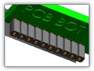 10 Position, Single RowA 10 position, single row, 834-43-010-10-001000 applied as a PCB bottom entry connector. | 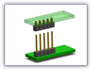 5 Position, Single RowA 5 position, single row, applied as a PCB bottom entry connector in a board stacking requirement |
Double Row Bottom Entry Application
An example of series 835 double row connectors being used as a bottom entry pass through connector for stacking two boards
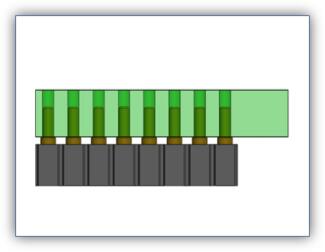 16 Position, Double RowDouble-row, 16 position, 835 series connector intrusive reflow soldered onto the bottom side of a .125” (3,18mm) thick PCB | 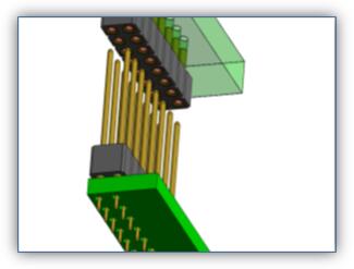 Board StackingA 16 position, double row, connector about to be applied as a PCB bottom entry connector in a board stacking requirement |
3 Board Stacking Application
Shown here is a three PCB module application using two Mill-Max 16 position, double row, 835-43-016-10-001000 connectors, stacked upon a long male pin header mounted on the base PCB.
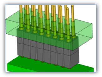 Engaged16 position male pin header engaged and passing through a 16 position, double row, PCB bottom entry connector | 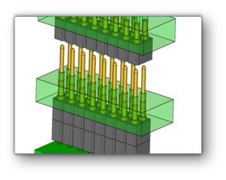 DisengagedTop PCB disengaged from this 3-board module application. |
Shown here is a three PCB module application using two Mill-Max 5 position, single row, 834-43-005-10-001000 connectors, stacked upon a long male pin header mounted on the base PCB.
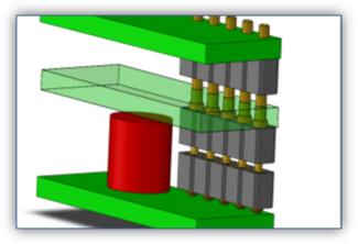 EngagedThe first connector provides clearance to the large red can device and provides a pass-through connection | 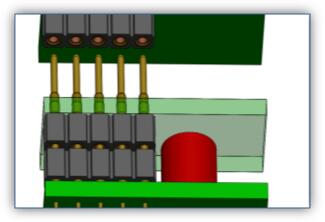 DisengagedTop PCB disengaged from this 3-board module application. |
Where the Sockets Are Used
- Low profile board stacking, where the .130” (3,302mm) above board height keeps the gap between PCBs tight.
- Piggyback module assemblies, in which a daughtercard sits above the base board and a single male header passes straight through it.
- Bottom entry connections, created by inverting the socket and mounting it beneath the PCB.
- Three board modules, using two sockets stacked on one long header, as shown in the examples above.
- Component clearance, where the long open tail spaces the boards far enough apart to clear a tall device between them.
- Field serviceable assemblies, where a stacked module needs to be separated without desoldering.
Selecting and Applying the Sockets
- Mating lead diameter. The receptacles accept round leads from .025” to .036” (0,635 - 0,914mm), which covers .030” (0,76mm) round pin and industry standard .025” (0,64mm) square pin headers.
- Header pin length. In a pass through stack the pin must seat in the receptacle and still clear the board above, so size the header for the full stack height rather than the first board alone.
- Orientation. Mounted conventionally the socket sits above the board. Inverted and mounted below it, the same part becomes a bottom entry connector.
- Board thickness. The 835 example above is intrusive reflow soldered to the underside of a .125” (3,18mm) thick PCB, so confirm the socket suits your own board and stack.
- Plating choice. Codes 43, 47 and 93 differ in shell and inner contact plating. Match the plating to your solder process and expected mating cycles.
Positions, Plating and Custom Configurations
Individual OFP® receptacles are available separately, in bulk or on tape and reel, and can be assembled into strip sockets to interconnect two or more circuit boards. Series 834 is offered in a wide range of single row lengths and series 835 in double row, both with plating codes 43, 47 and 93. Browse the 834 single row and 835 double row listings for available positions. If no standard part matches your receptacle size, position count, stack height or plating requirement, see custom capabilities or contact technical services.
Need help specifying a series 834 or 835 pass through socket?
Mill-Max engineers can review your stack height, position count, mating header and solder process, then recommend a single row 834 or double row 835 socket and the right plating code. If no standard part matches your board stack, we build to order.