
Introducing 4mm Pitch Power Connectors
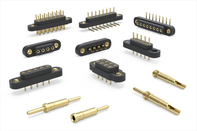
Sockets and headers designed for higher current and rugged applications.
Mill-Max introduces a new line of high-reliability, 4 mm (.157”) pitch sockets and headers designed for power connections and rugged field applications. The connectors combine high-current capability, mechanical robustness, gold-plated pins and internal contacts, mounting tabs with optional threaded inserts, and multiple termination styles to support reliable performance in mission-critical environments.
Addressing Critical Market Needs
As electronic systems demand higher power density and greater durability, designers need connectors that can handle elevated current, repeated mating cycles, and challenging operating environments. In energy and industrial systems, these connectors are used in motor drives, programmable logic controllers (PLCs), and solar inverters. Datacom and computing systems rely on them for server backplanes and power supply units (PSUs). Automotive and transportation applications include EV battery management systems (BMS), motor controllers, and lighting modules, while medical applications include heavy-duty imaging equipment.
The product line is intended for engineers and designers seeking precision-built connectors for higher-current and/or rugged applications, including board-to-board, wire-to-board, component-to-board, and cable-to-cable connections.
Key product features and benefits include:
- Efficient power delivery: Socket receptacles use Mill-Max #36 contacts rated at 16 amps (12.8 amps derated)1, with a maximum contact resistance of 10 milliohms to minimize temperature rise. They accept mating leads from .022” to .042” (.56 mm to 1.07 mm) in diameter and are rated for a minimum of 1,000 cycles, supporting a range of mating connectors for power and durability requirements.
- Durable mating interface: Headers feature .040” (1.02 mm) diameter mating leads to support high cycling, rough handling, and efficient power delivery.
- Secure mechanical attachment: All connectors include mounting tabs available with or without threaded inserts for attachment to printed circuit boards, housings, and cable assemblies.
- Greater pin spacing for power applications: The 4 mm (.157”) pin-to-pin spacing provides additional clearance to help manage electrical and thermal design considerations in higher-current applications.
- Flexible layout options: Single- and double-row connectors give designers options for different board layouts and available space constraints.
- Multiple termination choices: Through-hole, solder-cup, and right-angle terminations provide interconnect options for a variety of applications and orientations. Solder cups accept up to 20 AWG wire.
- High-temperature insulation: High-temperature molded nylon 4/6 insulators tolerate temperatures up to 290° C (554° F) and provide mechanical strength, electrical performance, and chemical resistance.
1 Per IEC 60512-5-1, Current Carrying Capacity, evaluated at 30 °C temperature rise.
Available Configurations
The 840 (single-row) and 842 (double-row) series cover headers and sockets across through-hole, solder-cup, and right-angle terminations. Build a part number from the family below.
| Part number | Configuration | Series details |
|---|---|---|
| 840-10-XXX-10-0Y2000 | Single row, header, through-hole mount | View details |
| 840-13-XXX-10-0Y1000 | Single row, socket, through-hole mount | View details |
| 840-10-XXX-00-0Y2000 | Single row, header, solder-cup termination | View details |
| 840-13-XXX-00-0Y1000 | Single row, socket, solder-cup termination | View details |
| 840-10-XXX-20-0Y4000 | Single row, header, right-angle, through-hole mount | View details |
| 840-13-XXX-20-0Y3000 | Single row, socket, right-angle, through-hole mount | View details |
| 842-10-XXX-10-0Y2000 | Double row, header, through-hole mount | View details |
| 842-13-XXX-10-0Y1000 | Double row, socket, through-hole mount | View details |
| 842-10-XXX-00-0Y2000 | Double row, header, solder-cup termination | View details |
| 842-13-XXX-00-0Y1000 | Double row, socket, solder-cup termination | View details |
XXX = number of positions
002 to 010 for the 840 series (single row); 004 to 020 for the 842 series (double row).
Y = threaded insert
Y = 0 for no insert, Y = 1 for a 4-40 threaded insert, Y = 2 for an M2.5 threaded insert.
Example
840-10-004-20-014000: single-row, 4-position, right-angle header with a 4-40 insert.
Sample part numbers and where to buy
Use the per-part links for the datasheet, 3D model, and live inventory. The full range of positions and insert options is available across the family above.
| Part number | Configuration | Datasheet, 3D model & buy |
|---|---|---|
| 840-10-002-00-012000 | Single row, solder-cup header, 2-position, 4-40 insert | |
| 840-10-004-00-012000 | Single row, solder-cup header, 4-position, 4-40 insert | |
| 840-13-002-00-011000 | Single row, solder-cup socket, 2-position, 4-40 insert | |
| 840-13-004-00-011000 | Single row, solder-cup socket, 4-position, 4-40 insert | |
| 842-10-004-00-012000 | Double row, solder-cup header, 4-position, 4-40 insert | |
| 842-10-008-00-012000 | Double row, solder-cup header, 8-position, 4-40 insert | |
| 842-13-004-00-011000 | Double row, solder-cup socket, 4-position, 4-40 insert | |
| 842-13-008-00-011000 | Double row, solder-cup socket, 8-position, 4-40 insert |
Pricing and availability shown by distributors change over time. Use the Check stock links for current Mill-Max inventory.
Need technical help or a custom design?
Use the form below to contact Mill-Max Technical Services.