How to Use Pin Receptacle Carriers
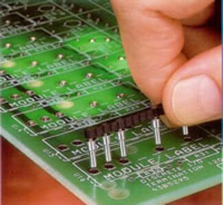
A receptacle carrier is a convenient way to pick-up and place individual sockets (receptacles) as a group. It is essentially an assembly fixture having an array of protruding pins, onto which are pushed individual receptacles.
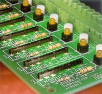
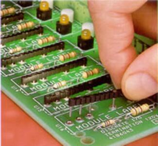
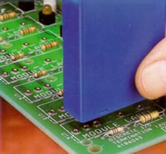
The receptacles are held in place by their internal spring contacts. The carrier assembly is placed into a corresponding group of holes on the circuit board, and the carrier holds the receptacles in position during the wave or reflow soldering cycle. The carrier is then removed after soldering, leaving behind a group of receptacles to be used as a socket for a leaded component.
 |  |
 |  |
Pin Receptacle Benefits
- Receptacle carriers are more convenient than placing individual sockets on a circuit board by hand with a pair of tweezers. At the other extreme, they do not require the expense of building a fully automatic assembly machine with a programmable X-Y table.
- Using a receptacle carrier eliminates the insulator of a traditional socket. For high-speed circuitry, this results in a shorter electrical path (lower inductance) and reduced propagation delay (no socket dielectric).
- Elimination of the insulator also provides lower socket profile. This is important for hand held devices such as mobile phones and PDAs, where space is at a premium and sockets are required for components that cannot go through reflow, such as speakers and microphones.
- Receptacle carriers are also ideal for socketing DCDC converters. One carrier can place the two different sizes of receptacle required by the power and control pins, while the receptacles themselves add very little to the height of the converter.
- Carriers are used primarily for wave soldering receptacles into . The added weight of the carrier "holds-down" the components as the circuit board passes over the solder wave.
- Receptacle carriers are also used for surface mount assembly, the technique is called intrusive reflow. The carrier assembly is placed into plated thru holes on the circuit board, and solder paste adjacent to the holes is then reflowed before the carrier is removed.
Receptacle Carrier Options and Applications
Mill-Max Carrier Sockets are available in both industry standard device (DIP, SIP or PGA) footprints as well as non-standard footprint configurations (ie: for a DC-DC Converter). Most Mill-Max receptacles can be configured into a Carrier Socket device pattern.
Mill-Max utilizes molded thermoplastic insulators for industry standard device footprints and machined FR-4 insulators for non-standard footprint patterns. Virtually any device can be configured into a Mill-Max Carrier Socket. Contact Mill-Max Technical Services and let our Applications Engineers assist you in designing a Mill-Max Carrier Socket which will improve the effectiveness of your assembly operation.