
Introduction to Omniball® Spring-Loaded Contacts and Connectors
Many interconnect designs require components to slide, rotate, or engage at non-axial angles, conditions that can challenge traditional spring-loaded contacts. When side loads are introduced, conventional plunger-style pins may experience increased wear, binding, or reduced electrical consistency over time. The Omniball® spring-loaded contact was developed to address these challenges by enabling reliable electrical connections in applications where motion is inherent to the mating process. Spring-loaded contacts of this type are widely known as pogo pins, and the Omniball® contact is a pogo pin variant built specifically for motion. This notebook provides an overview of Omniball® technology, its design characteristics, and guidance for engineers considering its use.
What Is an Omniball® Spring-Loaded Contact?
Omniball® contacts are spring-loaded pins, or pogo pins, that utilize a gold-plated rolling ball interface in place of the traditional sliding plunger. When engaged, the ball compresses under spring force and rolls across the mating surface, allowing electrical contact to be maintained while accommodating lateral, rotational, or angular movement. The Omniball® product line includes discrete spring-loaded pins as well as connector assemblies that package multiple contacts into defined layouts. These configurations allow the rolling contact technology to be applied across a wide range of mechanical form factors and interconnect requirements. | 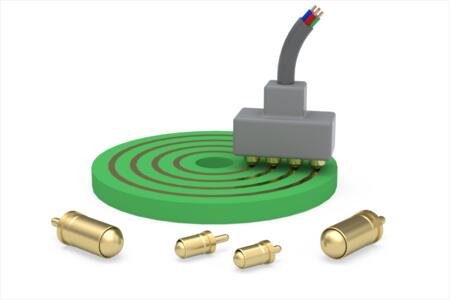 PRODUCT LINEOmniball® spring-loaded contacts. |
Omniball® products are available as:
- Discrete spring-loaded pins
- Single-row and double-row connector assemblies
- Circular multi-pin connectors
Key Design Features
| Omniball® contacts are manufactured using precision-machined components with gold plating applied to all current-carrying surfaces. This construction supports low contact resistance, corrosion resistance, and consistent electrical performance throughout the product life. The rolling ball interface reduces friction associated with side loading and has been validated through testing that includes up to 1,000,000 compression cycles, as well as extensive rolling motion under load, while maintaining specified electrical characteristics. |  PATENTUS Patent 11,509,087 B1. |
- Rolling ball contact interface enables sliding and rotational engagement without binding
- Gold-plated components for low contact resistance, corrosion resistance, and long service life
- Precision-machined construction with stainless steel internal springs
- High durability, tested to 1,000,000 compression and rolling cycles while maintaining electrical specifications
- Patented rolling ball design, US Patent 11,509,087 B1
Termination & Configuration Options
| To support diverse assembly requirements, Omniball® contacts are offered with surface mount, through-hole solder tail, and solder-cup terminations, enabling designers to integrate Omniball® technology into both PCB-based and cabled interconnect systems. | 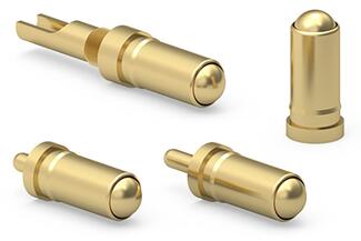 TERMINATIONSOmniball® with solder cup and solder tail. |
Termination Styles
- Surface mount (SMT)
- Through-hole solder tail (multiple tail lengths)
- Solder-cup wire termination (up to 20 AWG)
Configurations
- Discrete pins for custom layouts
- Single-row connectors (2–10 positions)
- Double-row connectors (4–20 positions)
- Optional threaded inserts and SMT alignment pegs for ruggedized designs
Omniball® Specifications by Series
Not all Omniball® pins are the same. The line splits into three groups: a standard series, a low-profile series for height-constrained assemblies, and a large-scale series with twice the stroke and a higher current rating. All three share the same .091” (2,311mm) rolling ball interface, so the difference is in stroke, force, current and height rather than in how the contact mates.
| Specification | Standard | Low profile | Large scale |
| Series | 0945, 7945, 7949 | 7935, 0945-1 | 0845, 7845 |
| Spring | 09, beryllium copper | 06, stainless steel | 52, stainless steel |
| Ball diameter | .091” (2,311mm) | .091” (2,311mm) | .091” (2,311mm) |
| Maximum stroke | .030” (0,762mm) | .030” (0,762mm) | .060” (1,524mm) |
| Rated travel (mid-stroke) | .015” (0,381mm) | .015” (0,381mm) | .030” (0,762mm) |
| Initial force (pre-load) | 30g | 20g | 22g |
| Force at mid-stroke | 55g | 60g | 72g |
| Maximum current | 9A | 8A | 13A |
| Derated current (20%) | 7.20A | 6.40A | 10.40A |
| Contact resistance | 30mΩ max | 20mΩ max | 20mΩ max |
| Max operating temp at max current | 120°C | 150°C | 150°C |
| Above-board height | .266” (6,756mm) | .208” (5,3mm), 7935 | .384” (9,75mm), 7845-0 |
Current ratings are at a 30°C temperature rise per IEC 60512-5. Operating temperature range is -55 to +125°C across all three. Above-board heights are for the parts named. Values from the Mill-Max datasheets for 0945-0-15-20-09-14-11-0, 7935-1-15-20-06-14-11-0 and 7845-0-15-20-52-14-11-0.
Discrete Pin Part Numbers
| Part number | Termination | Series | Packaging | Details |
| 0945-0-15-20-09-14-11-0 | Surface mount | Standard | Bulk | Product Details |
| 0945-0-57-20-09-14-11-0 | Surface mount | Standard | Tape and reel, 750 per reel | Product Details |
| 0945-1-15-20-06-14-11-0 | Surface mount | 06 stainless steel spring | Bulk | Product Details |
| 7945-1-15-20-09-14-11-0 | Through-hole, .079” (1,999mm) tail | Standard | Bulk | Product Details |
| 7945-2-15-20-09-14-11-0 | Through-hole, .118” (3,000mm) tail | Standard | Bulk | Product Details |
| 7949-0-15-20-09-14-11-0 | Solder cup, up to 20 AWG | Standard | Bulk | Product Details |
| 7935-1-15-20-06-14-11-0 | Through-hole, .079” (2,0mm) tail | Low profile | Bulk | Product Details |
| 7935-2-15-20-06-14-11-0 | Through-hole, .118” (3,0mm) tail | Low profile | Bulk | Product Details |
| 0845-0-15-20-52-14-11-0 | Surface mount | Large scale | Bulk | Product Details |
| 7845-0-15-20-52-14-11-0 | Through-hole, .150” (3,81mm) tail | Large scale | Bulk | Product Details |
The 7935 pins mount into a .044” (1,118mm) plated through hole and the 7845 into a .054” (1,372mm) hole. The 7949 solder cup presses into a .079” (2,007mm) non-plated through hole and carries both a barb and an anti-rotation knurl.
Connector Part Numbers
Omniball® connectors package the contacts on a 4mm (.1575”) pin spacing in single row, double row and circular arrangements, in through-hole or surface mount termination.
| Configuration | Part number | Notes |
| Single row, 2 to 10 positions | 845-22-0XX-10-0X1101 (through-hole), 845-22-0XX-30-XX1101 (surface mount) | 4mm (.1575”) pin spacing, .266” (6,76mm) above-board height, Nylon 4/6 insulator |
| Double row, 4 to 20 positions | 847-22-0XX-10-0X1101 (through-hole), 847-22-0XX-30-XX1101 (surface mount) | 4mm (.1575”) pin spacing, .266” (6,76mm) above-board height, Nylon 4/6 insulator |
| 4-pin circular | 945-22-204-30-360101 (tube), 945-22-204-30-360191 (tape and reel) | Surface mount, machined FR-4 epoxy insulator, 3.5A continuous and 5A peak per contact, 100Vrms/150Vdc |
XX in a connector part number is the position count. Threaded inserts are available for ruggedized mounting, and alignment pegs for the surface mount versions. The 4-pin circular connector carries its own current and voltage ratings, which differ from the discrete pin ratings above.
Explore available Omniball® product configurations or Contact Mill-Max Technical Services.
Explore Omniball® PinsExplore Omniball® Connectors
Why Use a Rolling Ball Contact Instead of a Plunger?
The rolling contact interface allows Omniball® contacts to maintain electrical continuity while accommodating motion between mating components. This characteristic helps extend service life in applications where connectors are subjected to repeated sliding or rotational engagement.
By maintaining consistent contact force during movement, Omniball® technology supports stable electrical performance in dynamic interfaces where uninterrupted signal or power transmission is required.
- Maintains electrical continuity during sliding and rotational motion
- Reduces wear, binding, and structural stress
- Simplifies mechanical tolerancing in dynamic assemblies
- Enables higher reliability in applications where axial mating is impractical
Typical Applications
Omniball® contacts were developed with motion-centric applications in mind, including sliding and rotating interfaces that challenge traditional connector designs. Examples include:
- Twist-and-lock cable connectors
- Docking stations and quick-connect mechanisms
- Blind-mate interfaces
- Circular and threaded connectors with rotational mating
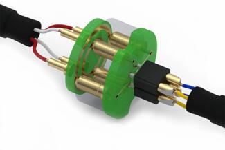 ROTATIONALOmniball® rotational application. | 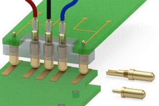 DISCRETE PINSOmniball® discrete spring-loaded pins in a sliding application. | 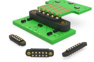 CONNECTOROmniball® connector in a sliding application. |
Industries Served
Industries that require reliable electrical connections under mechanical motion benefit from Omniball® technology. These include industrial automation, data infrastructure, and ruggedized electronics, where connectors may be exposed to frequent mating cycles or mechanical tolerance variation.
Medical and imaging equipment applications also leverage Omniball® contacts, particularly where precision motion and electrical reliability must coexist within compact assemblies.
- Industrial automation
- Data centers and server infrastructure
- Medical and imaging equipment
- Aerospace, defense, and ruggedized electronics
Design Considerations for Engineers
When selecting an Omniball® solution, engineers should evaluate the type and range of motion expected during mating, along with the required current rating and stroke length supported by different Omniball® series. Product variants include low-profile designs as well as versions offering increased stroke and current capacity.
Mechanical retention, mounting method, and alignment strategy should also be considered, particularly in environments subject to vibration or repeated engagement. Connector-based Omniball® solutions can simplify these considerations by integrating alignment and mounting features into the assembly.
Does your interface slide, rotate, or mate off axis?
Motion type and range, stroke, current rating, and alignment strategy all shape which Omniball® series fits. Our engineers can work through those tradeoffs with you, or design a custom configuration when a standard layout will not do.