
Using Edge Mounted Pins for Board Interconnects
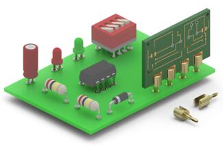
The Mill-Max family of PCB Edge Mount PCB pins are a fine example of Mill-Max ingenuity in designing and skill in manufacturing precision-machined pins.
Mill-Max bi-furcated pins have a .040” diameter to mate with a wide range of Mill-Max receptacles using our #34 contact. The pin mounts on the edge of a printed circuit board with the pin parallel to the board. The square section presses into a hole near the edge of the board, and remains secure prior to wave or reflow soldering.
This pin is widely used for the cable TV industry. It is commonly used in groups of 3 or 5 on the edge of a filter card used in CATV distribution amplifiers. The rugged design is ideal for field installation over the 20 year anticipated life of the equipment.
Slot Orientation and Alignment
Please note, for certain applications where multiple pins are used in-line, the slots must be oriented correctly otherwise an undesirable offset can result. For instance, in the example shown above, in order to prevent reducing the effective width of the slotted openings of the 3622 or a misalignment with the holes intended for the press-fit tail, the slots must be uniformly aligned. See the figures below illustrating these conditions.
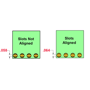 FIGURE 1Slot alignment. | 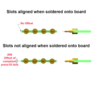 FIGURE 2Slot alignment when soldered on a board. |
Need help specifying edge mount pins for your board-to-board interconnect?
Our engineering team reviews your board layout, hole placement, mating receptacle, and slot orientation so in-line pins seat squarely and stay aligned through wave or reflow soldering. If a standard bi-furcated edge mount pin is not the right fit, we can review a modified or fully custom precision-machined pin for your application.