
Introduction to Swage Assembly

Swage assembly is a method of mechanically fastening pin terminals to a circuit board, similar in style to riveting. It is commonly used with solder terminals and printed circuit board pins for low to medium volume applications. The swaging technique captures the board between the flared or swaged material and the shoulder of the pin, fastening the pin to the board.The turret terminal shown to the right, commonly used to solder heavy gauge wires from a cable to a circuit board, is a typical example of a swage fastened pin.
The Swaging Process
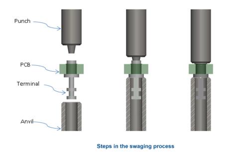
Swaging is accomplished by using a punch and anvil tooling with a manual or automatic press.
- The terminal is supported under the shoulder as it sits in the anvil,
- The hollow shank of the terminal is passed through the board hole.
- The swage punch forming tool is driven into the hole of the terminal, flaring out and compressing the protruding material to secure the terminal to the PCB.
- After installation on a board with plated through-holes and/or pads, the terminal is typically soldered to provide a reliable electrical and mechanical connection.
Mill-Max now offers Swage Tooling Kits for many of our standard Swage Mount Pins and Receptacles. To see our list of available tooling kits click the button below.
View Swage Tooling Kits By Part Number
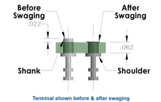
To ensure a successful swage with good retention, the following two conditions should be met:
- The pre-swaged terminal shank should extend at least .022" above the circuit board surface so there is sufficient pin material to form and flare;
- The circuit board hole diameter should typically be no more than .004" greater than the pre-swaged terminal shank diameter.
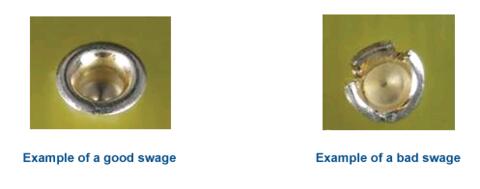
Note: to prevent cracking of the flared section of the terminal pin during forming, the Brass alloy pin material is annealed to a softer Rockwell Hardness (20-50 Rockwell B). MIL-T-55155 provides guidance for inspecting a swaged terminal.
Swaging Equipment
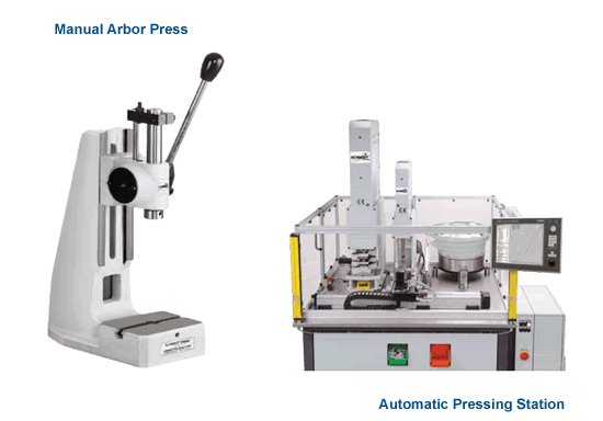
The type of arbor press, the punch and anvil tooling, and the sequence of the assembly process depend on the terminal chosen and the specifications of the PCB. Sometimes the pins are pushed into the board holes first, while other times the pins maybe placed in the anvil and then the board set on the pins. In any case, the swage punch tool is driven into the hole and flares out the material of the supported terminal to fasten the pin to the board.
Factors to consider:
- Tooling clearance. Are there devices or other obstructions near the swage pin that could interfere with positioning the swage tooling?
- Board support. Can you support the board well enough to prevent bowing or breaking during the press stroke
- Shank protrusion. Does your board thickness, including tolerance, leave at least .022" of terminal shank above the board surface?
- Single pin or array. Are you swaging one terminal or a group of them? This determines whether you need a single swage punch or a ganged punch.
- Production volume. How many pins do you have to swage? Manual, semi-automatic, and fully automatic presses are available in a range of sizes and pressing capacities.
Next Section
Mill-Max Swage Tooling Cross Reference
Continue on to the complete list of swage kits available from Mill-Max. Each kit contains one punch and one anvil. Look up your basic part number, the first four digits, to find the matching kit number and ordering details.