Glossary
- Annealing
A heat treatment process that alters the physical and sometimes chemical properties of a material to increase its ductility and reduce its hardness, making it softer and more workable. It involves heating a material above its recrystallization temperature, maintaining a suitable temperature for a specific amount of time, and then cooling. Mill-Max brass pins and receptacles are often annealed to make them easier to crimp, rivet (swage) or bend.
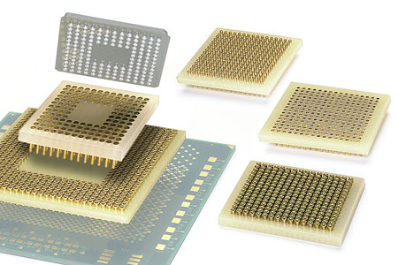
- Ball Grid Array (BGA)
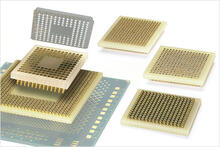
A surface mount packaging for integrated circuits (ICs) such as microprocessors. The bottom of the package features a high-density array of solder balls or preforms to make connections to a PCB. Mill-Max offers a two-piece adapter system for making BGA devices pluggable; This consists of a male header which mounts to the preforms on the underside of the BGA, as well as a female socket to mate with the header. Standard pitch options are .8mm, 1mm, and .050”. Learn More
- Barb

Sometimes referred to as a fish-hook, a barb is a common press-fit feature machined on many pins, receptacles, and spring pins. This feature is used predominately to retain products in non-plated through holes such as ones in insulators or plastic housings. A barb retains a product by ”biting” into the sides of the mounting hole during assembly, generating an interference fit between both components. Barbs do not offer any anti-rotation properties, so a knurl retention feature is often used instead when this is a firm requirement.

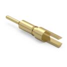
- Bi-furcated

A horizontal slotted feature intended for edge mounting. The location of the slot lends itself to being utilized in applications requiring parallel board mounting.
This feature is also machined with two flats, allowing the component to be partially press-fit into the board prior to soldering. Learn More

- Blind Mate
Mating of one or more components where visibility is obstructed or limited.

Typical Blind Mating Connection This process can lead to damage or breakage due to misalignment during mating. To mitigate this risk with pin + receptacle connections, receptacles with generous countersinks/lead-ins are used along with alignment pegs and/or shrouded housings to further guide the mating pin to the center of the receptacle. Spring loaded connections are better suited for blind mates due to the lack of insertion required. Furthermore, customers have used target pins with a concave face to help guide the plunger component of the spring pin towards the center of the target.

- Body
Refers to the central section of a pin, receptacle, or spring pin. Typically machined out of a brass alloy material.
- Bottom Entry Receptacle
Typically, Mill-Max receptacles are assembled into a PCB with the contact clip towards the top of the board, and the mating lead being driven from the top-down. In bottom entry receptacles, the clip is loaded into the bottom end of the shell (side opposite the shoulder). When this style of receptacle is assembled into the board, the lead must be inserted upwards from the bottom of the board. View Examples.
- Bulging

A slight and uncontrolled deformation of the receptacle shell that might occur after a contact clip is inserted during the receptacle assembly process. Most commonly a result of the receptacle shell having a thin wall, which is due to the coaxial hole diameter and the outer diameter being comparable in value. Typically results in a .001”-.003” increase in the outer diameter of the receptacle shell located near the contact entrance. Can typically be averted by adding a shoulder to the receptacle shell or increasing the thickness of its walls.

- Carrier/Transporter
An assembly consisting of an insulator with male dummy pins onto which discrete receptacles are loaded. This assembly is employed as a fixture during a soldering operation and is subsequently removed leaving a PC board populated with individual receptacles. Carriers that load male pins are also available for special applications as custom/made to order solutions. Learn More.
- Clip (Contact)

The multi-finger spring insert component of a receptacle assembly. Its primary function is to generate the electrical and mechanical connection between a female receptacle and its mating male pin or lead. This is achieved by means of the fingers or tines of the component, which grip the pin/lead upon proper insertion and allow for multiple insertions.
Contact Clips are stamped and formed from Beryllium Copper or Beryllium Nickel for high temp applications. Learn More.

- Closed Bottom

A type of receptacle whose body is closed or sealed on the side opposite the contact clip. This allows the mating pin or lead inserted to “bottom out”, meaning that it is inserted to the point where it is contacting the bottom surface. While this has no bearing on the performance of the product, “bottoming out” does provide the user a simple method of determining whether the receptacle is completely capturing the mating lead. A closed bottom part also eliminates the concern of solder wicking up the bottom of the part during soldering procedures such as wave or reflow. View Examples.

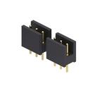
- Closed Frame
A type of DIP insulated housing that does not include an open mid-section or window. This solid surface makes the connector better suited for automated handling such as with a vacuum nozzle. View Examples
- Compliancy
A contact clip's ability to accept multiple insertions and extractions of a wide range of pin shapes and sizes while retaining its original configuration. The acceptance range of the contact will typically be altered after inserting the maximum permissible pin. For example: the #34 contact has an initial operating range from .032" to .046" diameter pins and a compliancy of .010”. After insertion of a .046" pin, the contact is sized, and the minimum pin acceptance becomes .046" - .010" = .036". Thus, the new operating range becomes .036" to .046". The compliancy rating advertised for each of our contacts can be found on the General Contact Information page of our Catalog.
- Compliant Press Fit
A method of mounting an interconnect component into a plated through hole on a PCB using a feature that consists of multiple barbs that are machined on a hollow slotted tail. This termination feature is designed to collapse and conform to the parameters of the plated hole, preventing damage while ensuring a reliable solderless gas-tight connection. Common customer applications include multi-layer board stacks and mating card-edge to card-edge connections. Learn More
- Constant Usage Temperature (CUT)
Constant Usage Temperature is a measure of the maximum temperature that a material may be exposed to for long periods of time, 1000-1500 hrs., before degradation of its electrical and mechanical properties occurs.
- Contact (and Contact Clip)
The multi-finger spring insert component of a receptacle assembly. Its primary function is to generate the electrical and mechanical connection between a female receptacle and its mating male pin or lead. This is achieved by means of the fingers or tines of the component, which grip the pin/lead upon proper insertion and allow for multiple insertions.
Contact Clips are stamped and formed from Beryllium Copper or Beryllium Nickel for high temp applications. Learn More.
- Contact Rating
Current carrying capability of a contact measured in amperes with respect to temperature rise above ambient.
- Contact Resistance
- A measure of how difficult it is for current to travel/pass through an electrical interface (may consist of components such as pin + receptacle and/or spring pin + target connector). A higher contact resistance is undesirable because the connection would be more inclined to resist electrical flow. Measured in ohms, this characteristic is impacted by both mating component’s geometry, plating, contact area and normal force. The actual interface typically consists of a contact area much smaller than what is seen by the naked eye, and results in a resistance value that is independent of the standalone resistance for each material in the mated set. An observable voltage drop across the connection occurs due to this resistance.
- Contact Sizing
- A value-added process that can be provided to discrete receptacles or socket connectors, typically to yield lower insertion/extraction forces. Prior to the parts being received by the customer, a pin lead with a diameter on the higher end of the contact clip’s acceptance range will undergo one mating cycle with the product. This process slightly pushes open the fingers of the clip, resulting in a looser fit-up with the mating lead upon subsequent cycles.
- Coplanarity
The measurement of multiple points and their distance from a single common plane. Used for surface mount connectors to ensure that all individual pins, receptacles, or spring pins in the array make uniform contact to the board within a certain tolerance. Poor coplanarity may lead to uneven or detached solder joints once the part is assembled onto SMT pads.
- Crimp Termination

A feature provided on certain pins, receptacles, and spring pins that allows for solderless wire termination by deforming the outer diameter of the product. The crimp parts will have a barrel on one end with a blind coaxial hole drilled into it, creating a thin wall which allows the material to be pinched or deformed. These features can accept a range of wire gauges while ensuring proper fit up for greater versatility. After a properly sized wire is inserted into the feature, the retention deformation is generated by use of a crimp tool and positioner. Validation of the retention force between the wire and the product can be evaluated by methods such as a pull test. Learn More
For more information view the following video, .

- Current Rating
Current carrying capability of a product measured in amperes with respect to a specific temperature rise. For Mill-Max products, the current rating has been specified with a conservative 10°C temperature rise (Tested at room temperature, 20˚ C). The current rating advertised for a product can be found on the specific product’s webpage on our website. Please note that this performance characteristic is not specified for male pins and male pin headers. Theoretically, the amount of current that can be passed through a male pin can be increased until the heat generated reaches the melting temperature of the pin material. In practice this is limited by other elements in the circuit such as the PCB, the mating receptacle or socket and active components. To evaluate the heat generated in a pin due to an applied current, the resistance of the pin is required. The formula below can be used to calculate the resistance (in ohms) of a pin. The table below provides the resistivity values for the materials Mill-Max uses along with thermal properties that may be useful for further heating calculations.
R=(ρ*L)/A: where R is resistance; ρ is electrical resistivity of the material; L is the length in feet and A is the area in circular mils.
Material
Resistivity (ρ) ohms
(circ mil/ft) @68˚F
Thermal Conductivity
(Btu/sq ft/ft hr/˚F @68˚F)
Thermal Capacity
(Btu/lb/˚F @68˚F)
Brass 360 & Brass 385
37-40
67
.09
Phosphor Bronze Alloy 544
54.6
50
.09
Tellurium Copper Alloy 145
11.2
205
.092
- Cut-off Burr/Nib
- A small remnant of material left behind on a part as a byproduct of machining. Typically located on the face being cut to separate from the remaining bar stock. Cleaning & deburring operations help to smooth out this bump/protrusion. In applications which require more of a flush surface, the cut-off can be delegated to the less critical side of the part or removed by making a small indent in its place.
- Cut-out Window
- The removal of material (typically in the center of an insulator or housing) which allows for improved visibility and the ability to place components in the open section. Most commonly provided on BGA and PGA style connectors.
- Cycle
One complete mating sequence between two interconnect components. A cycle between a pin and receptacle combination refers to one full insertion and extraction of the pin into the contact clip of the receptacle.

One Pin/Receptacle Cycle A cycle between a spring pin and target pin/pad combination refers to one compression of the plunger onto a target, typically to half-stroke, followed by a return to the uncompressed state

One Spring-Loaded Compression/Cycle


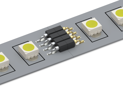
- Daisy Chain
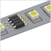
Interconnect components mated horizontally in series to form a longer sequence. Most often performed to bridge a gap between boards or extend the connectivity of a device using horizontal mount header & socket combinations. Certain spring-loaded connectors can also be used for daisy chaining by mating the plungers of one against the bases of another.
- Discrete
- Referring to an individual pin, receptacle, or spring pin component rather than an assembled connector. A connector assembly is created by loading one or more discrete components into an insulated housing. Discrete components can be better suited for inconsistent and non-standard footprints, or applications where a housing would interfere with the neighboring or mating components.
- Double Action
A spring pin that is manufactured with two plunger components, allowing for actuation on both sides of the product. These plungers share the same internal spring, so the travel distance is cumulative between both components. This type of product is an appealing solution for applications that require either a temporary or permanent connection between two parallel boards or devices without the use of solder. View examples.
- Double Tail (Header) Pin

A male pin that has been machined with tails on both ends. The most common usage for this style product is for one tail to be solder mounted into a through hole on a PCB, while the other is used as a lead for mating into a female interconnect component such as a receptacle or socket. However, the product can also be utilized to generate an electrical connection by solder mounting it into through holes on two separate PCBs or by mating it between two female receptacles or socket components. This style product is often designed with a press-fit retention feature, allowing for assembly into an insulated housing to form a male header. The tails can either be identical on both ends or have differences in their diameters and lengths, allowing for further versatility. View Examples

- Dual Entry Receptacle

A receptacle containing contact clips at both openings or containing an individual contact clip that is suitable for either top or bottom entry. Allows for more versatile use when compared to single entry female receptacle products. View Examples

- Dual Inline Package (DIP)
An interconnect component that consists of a rectangular insulator with two parallel rows populated with either male pins or female receptacles. These products are designed to mate with equivalently spaced electronic packaging components or designed to generate a comparable footprint to these products on a PCB. Commonly specified with pitch/pin-to-pin spacing of .100”, .070” pitch spacing options are offered for shrink DIP package applications. The parallel rows are offered in more varied spacing options, typically ranging from .200” to .900”. Offered in a variety of termination styles including solder tail, SMT, wire termination, and press-fit options. View Examples
- Durability
- A product’s anticipated mechanical life expectancy. Typically refers to the insertion/extraction cycles of a receptacle or the compression cycles of a spring pin. The actual mechanical life is a factor of several application-specific variables, such as the environmental conditions and/or mating pin specifications.
- Early Engagement

A contact clip designed to form a strong connection with a mating lead/pin without needing to pass the full length of the contact clip. Useful in applications where the mating lead is short in length. View Examples

- Edge Mount
A pin termination style which captures the edge of a PCB with a solder connection or mechanical fastener. These pins often have a tail to allow perpendicular connection with another board or device. Useful in applications where a circuit board needs to be cyclable, such as in mother-daughter card applications. View Examples
- Electrical Discontinuity
- A break or interruption in the flow of current in an electrical connection or circuit. Can be indicative of failure or damage to a component within the application, or from excessive shock and vibration.
- Electro-Vibratory Plating
- An electroplating system where the parts are processed in a vibrating basket which ensures uniform plating thickness and avoids damage to delicate parts.
- Electroless Plating
A plating method where material is applied to a part using acid or solutions. This method primarily differs from an electroplating operation in that an electric current is not used to induce the plating deposit generation.
- Electromechanical
To relate to or involve an electrically operated mechanical device
- Electroplating
A plating method where material is applied to a part by means of electrodeposition. This commonly involves loading parts into a vibrating basket that is immersed in a plating solution and then applying an electrical current to induce adhesion. Benefits of electroplating include uniform plating thickness, improved plating coverage in small coaxial holes, and preventing damage to delicate parts.
- Electrostatic Discharge (ESD)
The momentary electric current that flows between two objects that may cause damage to electronic equipment.
- End Stackable
A connector where the dimensions and tolerances of the insulator are precise enough to stack multiple connectors from end-to-end while maintaining the same pin-to-pin spacing throughout adjacent connectors.
- Extraction Force
Sometimes known as the withdrawal force, this is the force required to remove a mating lead or pin from a contact clip. The value of this force is primarily driven by factors such as the specific contact clip selected, the base material of the contact clip, and the shape and diameter of the mating lead. The extraction force is also typically lesser in magnitude when compared to the same contact clip’s insertion force. Graphs illustrating the extraction forces for each contact clip can be found online or on the Receptacle Contact Data catalog pages.
- Fibre Plug / OFP® Solder Barrier

An organic paper plug used to create a solder barrier in open bottom receptacles. Designed to help prevent solder from wicking up the barrel of the receptacle during a reflow soldering operation. Once soldering is complete, the mating lead knocks the plug out of the receptacle upon insertion and the plug can be discarded. Learn More.

- First Make/Last Break
A connector product where certain positions are designed to engage first and disengage last. This is used for applications where the order of engagement is critical, such as types where the ground connection must be established first and released last to prevent damage to the system.
- Flange (Shoulder)

An external rib or lip machined on most pin, receptacle, and spring pin components that is typically the largest external diameter. Most often located on one end of the part but can also be found near the center in certain designs. Its primary function is to assist in board assembly by orienting the product in the mounting hole and providing added support during solder or press-fit mounting. In spring pin and receptacle products, this feature also plays a pivotal role in the assembly of the component.

- Flash (Plating)
- A very thin layer of plating, usually less than 10 micro inches in thickness. Switching to flash plating from a thicker plating option is a common way to drive down the cost of a component, possibly at the expense of durability. This makes flash plating better suited for applications with benign environments that will not see aggressive handling or in ones where gold embrittlement is of concern.
- Flatness
Sometimes used in place of coplanarity, flatness refers to the amount of variation of a plane or surface.
- Floating Contact

Refers to connectors that contain pins or receptacles designed to move up and down freely in an insulator, rather than being retained in place by a press-fit feature. This additional “play” allows the connector to compensate for unevenly dispensed solder paste, mating misalignment and other errors known to increase the amount of stress applied to the connector, PCB and/or solder joints. View Examples.

- Free Machining Alloy
An alloy which incorporates additives to make the material easier to machine, providing better surface finishes and increasing tool life. Mill-Max uses free machining Brass alloys with lead as the additive. Learn More
- Fretting
A form of wear that often leads to or increases the likelihood of corrosion. This wear is often caused by the repeated cyclical rubbing between two surfaces in which one is under a load. In pin & receptacle connections, this wear is often generated between the internal contact clip and the surface of the mating pin. In spring loaded connections, this wear is generated between the plunger of the spring pin and the mating surface or target. Over time, this wear results in the removal of material from one or both mating surfaces, resulting in the appearance of black spots, marks, lines or patches depending on the specific mode of fretting wear. As more debris is accumulated, the wear process by abrasion is accelerated which can then accelerate oxidation as more of the protective layer is removed.
- Gas Tight Connection
An electromechanical connection of sufficient pressure that prevents the intrusion of a corrosive atmosphere into the contact area.
- Gold Plating
Gold is commonly used as the top plate for many different interconnect components and electronic devices. Mill-Max offers standard gold plating options ranging from a flash plating to 50 µin minimum, with options for both nickel and copper underplates; customer-specific plating finishes are also available upon request. Benefits of a gold-based finish include low and stable contact resistance along with superior protection against corrosion. Application-dependent factors such as environment, cycle life, concerns of gold embrittlement and cost can help decide which thickness option to use for the gold layer.
- Gull Wing

A SMT termination style that is commonly utilized in Mill-Max connectors. A gull wing termination is characterized by the solder tails of the populated pins or receptacles being bent outward, resembling a gull. These bent tails are surface mounted to the board via rectangular solder pads specified prior to soldering. This termination style results in increased solder joint strength and permits easy visual inspection of said joints. Mill-Max offers gull wing SMT termination options in both male and female interconnect packages, including DIPs and single & double row SIPs. Learn More.

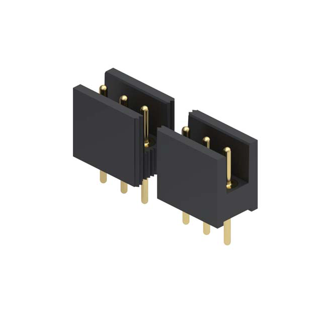
- Header
A male interconnect component which is comprised of discrete pins assembled into a plastic insulated housing. One end of the product is manufactured with a post/lead, designed to act as the mating half to a suitable female socket with an appropriate pitch and acceptance range. Offered with various lead diameters, grid spacings/pitch, position counts and mounting styles; custom designs can also be explored upon request. View Examples
- Heat Deflection Temperature (HDT)
An industry recognized test for comparing the short term effects of high temperature on plastics.
- Heat Treating
- The process of using specific heating and cooling cycles to alter the mechanical properties of an alloy. Heat treating can harden or soften a metal depending on the parameters used and the desired physical property of the material within its application.
- Hex Press Fit

A hexagonal cross section machined around the body of a receptacle or pin providing a retention feature for press-fitting in a PC board with a Plated Through Hole. It can also prevent rotation of the pin, while still maintaining a Gas Tight Connection. View Examples.

- High Speed Turning
Also known as high speed machining, this manufacturing process uses rotating stock, cutting tools, and bits to create interconnect components such as pins, receptacles, and spring pins. This process allows for ultra-tight tolerances, smooth finishes, and unsurpassed quality. Learn More
- High Temperature
Parts designed to withstand higher temperatures than what is specified for the standard lineup. This often involves replacing a material in the part/assembly with an alternative that is better suited to withstand stress relaxation due to heat. Mill-Max currently offers a line of high temperature receptacle products which use a contact clip fabricated out of beryllium nickel as opposed to beryllium copper; which are rated for “down-hole” and “burn-in” applications up to 300°C. In spring-loaded applications, Mill-Max offers higher temperature options in the form spring pins constructed with stainless steel springs.
- Horizontal Mount
Components which are intended to be mounted horizontally or parallel to the board surface. Often provided in different styles, including surface mount (HSMT), Z-bend, and right angle through-hole.
- Initial/Pre-Load Force
The force required to begin actuating/compressing the plunger component of a spring-loaded product. The value of this force is dependent on the specific spring used in the assembly.
- Injection Molding
A molding method whereby granular plastic is heated to a molten state and injected into a mold cavity. The plastic solidifies to the shape of the cavity upon cooling and is promptly ejected. Standard Mill-Max connectors use various injection-molded housings which are press-fitted with discrete components. Custom injection-molded housing designs can also be explored upon request.
- Insertion Force
The force required to insert a mating pin or lead into a contact clip. The value of this force is primarily driven by factors such as the specific contact clip selected, the base material of the contact clip, and the shape and diameter of the mating lead. The force of the initial insertion will typically yield the greatest amount of force, as the mating lead is opening the fingers/tines of the contact for the first time. The insertion force is also typically greater in magnitude when compared to the same contact’s extraction force. Graphs illustrating the extraction forces for each contact clip can be found online or on the Receptacle Contact Data catalog pages.
- Inspection Hole

A hole drilled on the side of certain wire termination parts which provides internal visibility. This can be used to verify that a wire has been successfully assembled to the part, whether by a crimping or soldering operation. View Examples

- Insulator
- A molded or machined plastic dielectric housing which retains a single interconnect component or a multi-position array in a connector assembly. Depending on the requirements of the application, these housings can have different external dimensions, footprint patterns, and include additional features such as a cut-out window, stand-offs, or alignment pegs. Mill-Max typically uses molded plastic insulators for standard connector products, but has the capabilities to provide customer driven solutions with either molded or machined plastic housings.
- Interconnect
Connector products comprised of pins, receptacles or spring pins loaded pins into an insulated housing, designed to form a permanent or cyclable electrical connection with a corresponding mate. Pin + receptacle connections are made using a male header in combination with a female socket, commonly offered in SIP and DIP style packaging. This differs from spring-loaded interconnect pairs, where a spring-loaded header is mated with a target connector. Applications include board-to-board connections, along with wire-to-board, device-to-board, cable-to-board, and board stacking operations. Learn More
- IP Rating
Measurement of how well a piece of equipment or device can resist penetration of water, chemicals, dust and other fluids or debris. Sometimes known as the water resilience or level of ingress protection a product has.
- Jumper

A pin that is bent into a U-shape whose primary function is to bypass or connect a pair of uncoupled traces on a circuit board. These pins are currently offered discrete or assembled into insulated housings. View Examples

- Kapton
A polyimide film used to package and transport discrete interconnect components. Commonly used for semi-automated board assembly. View Example
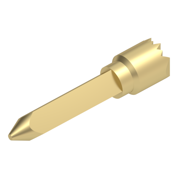
- Knurl

An array of vertical serrations machined around a diameter of an interconnect pin or receptacle, providing a retention feature for press-fitting into an unplated mounting hole in a PC board or insulator. This feature prevents the pin from rotating within the mounting hole, which may be beneficial in applications where alignment is critical. View Examples.

- Land/Pad
A typically round, flat, gold-plated conductive surface used as a mating interface for spring-loaded products. These pads are incorporated onto PCBs or electronic devices and allow for electrical connection as the plunger of a spring pin is compressed up against it. While thin pads can be generated during the board fabrication process, they may not provide the durability or adaptability required. In these instances, Mill-Max offers discrete target discs to provide a conductive surface equivalent to that of a pad, but in a more robust machined design. View Examples
- LCP (Liquid Crystal Polymer)
Classified as a thermoplastic, LCP is a hard, rigid material which exhibits outstanding strength at high temperatures and exceptional strength and toughness in its thin walls. Applications: LCP is used as an insulator material for tight grid (.050", 2mm) connectors and extremely high temperature requirements.
- Light Insertion Force (LIF)
Socket connector products where minimal force is required to mate and de-mate the mating component or device. Primarily used for high position count applications due to the cumulative nature of the insertion force, as well as applications with delicate or fragile mating pins or leads.
- Machined
Manufacturing process whereby a rapidly turning solid metal rod is cut to precise tolerances. This method lends itself to generating features commonly developed on a rotational axis, namely operations such as turning, facing, cutting, drilling, and knurling. Secondary processes allow for the implementation of more unconventional features, such as slots and/or backholes. Also known as .
- Machined Plastic Insulator
An insulator fabricated out of large rectangular sheets of plastic being machined with a high-speed drill/router. As there is typically no tooling or fixturing required for production, this type of insulator presents an appealing solution for lower volume production runs and/or rapid prototyping. FR-4 epoxy is the primary material used, with G-30 polyimide offering an alternative for higher temperature applications. Learn More.
- Mated Height

The assembled height of a pair of male and female interconnect components once engaged. Commonly considered a design constraint when developing PCB assemblies, careful selection of a suitable male + female combination is required to achieve proper stack up (or above-board distance). Mated sets of discrete components or connectors can be considered zero, low, mid, or high profile based on this amount of stack height.

- Mating Pin
A pin or lead used to mate with a female interconnect component by inserting into the contact clip. Critical features of this component include the diameter, length, shape of the tail or shaft and the plating finish. There may be a termination feature on the opposite end of the mating lead depending on the specific application.
- Max. Stroke

The maximum possible distance the plunger of a spring pin can be compressed or actuated. It is primarily dependent on the characteristics of the internal spring and the construction of the specific spring pin. While it is possible to compress a spring pin to this particular distance, it is not recommended in applications that are looking to maximize both mechanical and electrical performance. However, applications that require minimal cycling may see electrical benefits when compressing the spring pin to its maximum stroke or close to it.
- Mid Stroke/Rated Travel
Fifty percent (50%) of a spring-loaded pin’s maximum stroke capability. This is the minimum travel required to ensure the spring-loaded product meets all stated electrical and mechanical ratings and specifications. All ratings are generated from testing which is performed at mid stroke compression.
- Misalignment
Defined as incorrect or poor alignment between mating components, features, or products within an interconnect system. It can occur in pin & receptacle connections when the mating pin inserted at an aggressive angle. It can also occur in spring-loaded connections by exposing the plunger of the spring pin to a lateral or side load. While a small amount of misalignment is to be expected and acceptable during a mated connection, an excessive amount can cause significant damage to the mating components. This damage may present itself in the form of reduced component performance and/or premature failure.

Pin/Receptacle Misalignment 
Spring-Pin Misalignment


- Molded Plastic Insulator
An insulator fabricated by means of an injection molding operation. Most often specified for high volume applications and/or when certain complex features need to be included on the housing. Common material offerings include: PCT polyester, Nylon 46, and PPS (Ryton R-4-200).
- Mounting Hole
Hole(s) on a board, housing, or insulator used for the retention of a pin, receptacle, spring pin, or connector. Can be plated or left bare depending on the application or type of housing/part. The most critical specification for this feature is the diameter/hole size.
- Mounting Hole Size
Size call out for the mounting holes.
- Mounting Tab

A tab-like feature included on the ends of select insulated housings to allow for further mechanical retention to the PCB. These features include a hole that can either be provided bare to allow for addition of application specific hardware, or prepopulated with a threaded insert to allow for fastening with a screw or comparable threaded component. View Examples

- Nail Head Pins

A versatile male pin machined in the shape of a nail. Can be used for a multitude of purposes including board stacking, board to component connections, mating surfaces for spring loaded products, and many more. The main draw of this style of pin is its ability to provide a thru connection while having a low-profile head/largest diameter. View Examples

- Non-Plated Through Hole (NPTH)
- A mounting hole that has not been given a layer of plating on a PCB or housing, such as a molded or machined plastic insulator. When press-fitting, non-plated through holes are suggested for parts that have a barb or a knurl feature.
- Nylon 46
Classified as a thermoplastic, Nylon 46 offers superior heat resistance, good electrical properties and excellent toughness in its thin walls, which are desirable characteristics for connector insulators. Its superior strength in thin walls enables the press-fitting of pins in close proximity to each other without cracking or warping the material, making it ideal for molding 1mm, 2mm and .050" grid insulators. Nylon 46 is suitable for high temperature applications including vapor phase, infra-red reflow and wave soldering operations.
- OFP® Solder Barrier/Fibre Plug
An organic paper plug used to create a solder barrier in Open Bottom receptacles. Once soldering is complete, the mating lead knocks the plug out.
- Open Bottom

A receptacle shell which has a full length internal coaxial hole, making the component hollow or straw-like. This design allows the mating lead or pin to protrude through the receptacle upon insertion. This is especially appealing for pins or leads that are quite lengthy or those who need to be trimmed as a post insertion procedure. View Examples.

- Open Frame

A type of DIP insulated housing where there are one or more open/hollow sections in the center of the component, similar to that of a cut-out window. These features help minimize the amount of board space the connector takes up by allowing for additional components to be mounted to the board within these open sections. They can also aid in the inspection of the solder joints by providing further visibility when compared to a closed frame product. View Examples

- Operating Temperature
The specified timeframe and temperature range by which a part or device can safely function within. Applications should ensure staying within these limits for optimal performance and durability.
- Operating Travel Range
25% - 100% of a spring-loaded pin’s maximum stroke capability. This is the range of compression a spring-loaded contact may operate in. There are some products that may fall outside this range due to specific design characteristics. Note that at compression less than mid stroke the electrical and mechanical performance may not meet the stated specifications. Using spring-loaded contacts at maximum stroke there is a risk of over compression due to tolerance variation which may lead to damage of spring-loaded components and reduced mechanical life.
- Over Compression
The condition by which a spring pin or spring-loaded connector is actuated past its specified maximum stroke distance. Spring deformation can occur, causing it to bind and remain set/stuck in the same position without returning to its original uncompressed state. A compression of 50% of maximum stroke (rated travel) will ensure the spring-loaded pin meets the stated electrical and mechanical ratings and specifications. As plunger travel is reduced below 50% the electrical performance may degrade while mechanical life may be extended. The opposite is true for compression above 50% of maximum stroke.
- Packaging
- The method by which finished goods are enclosed and shipped to customers. Most discrete Mill-Max products are provided in bulk, which involves packaging the products in either sealed plastic bags, tubes, or cushioned boxes. However, more automation friendly options are provided as a value-added process; these include Kapton tape, tape and reel, and trays.
- Passive Device or Component
An electronic connector that consumes electrical energy, but does not produce electrical energy. Passive devices are not susceptible to significant ESD damage.
- PCB Connectors
PCB Connectors can be referred to as PCB Interconnects or Rectangular Connectors. Specific terms are also used for the two sides of the connection. Male PCB Connectors are often referred to as Pin Headers, as they are simply rows of pins. Female PCB Connectors can be called Sockets, Receptacles, or Socket Headers.
- PCT (Polycyclohexane Terephthalate)
Thermoplastic polyester is rated for higher temperatures. PCT is a standard material on DIP and SIP insulators for higher temperature operations. All PGA and surface mount products are molded from PCT and are suitable for infra-red, vapor phase and wave soldering.
- Pick & Place
An assembly process by which automated equipment is used to place a broad range of electronic components onto a printed circuit board quickly and precisely. A pick & place machine accepts tape & reel packaged parts, which are extracted individually from their tape pocket by a robotic arm fitted with a nozzle, and mounted in the desired location on the PCB. Parts may be assembled with a pick & place clip, typically removable, which provides a flat top surface for improved handling. Learn More
- Pick & Place Cap/Clip

A removable molded plastic cap or clip component provided on certain products packaged on tape and reel. The primary function of this component is to aid in the removal of the part from the carrier tape. It provides a larger surface area for handling and keeps the part centered in the pocket. This component is typically left on the product during the soldering portion of the board assembly procedure, but it is removed shortly after the installation is completed. View Examples

- Pin Grid Array (PGA)

A type of processor packaging which offers high-position, customizable arrays of pin/receptacle connections spaced .100” (2.54mm) apart and housed in a square or rectangular insulator. Mill-Max offers PGA style headers, sockets, and carriers for surface mounting, through-hole mounting, or wire-wrap termination. View Examples

- Pitch/Grid/Spacing
- A pre-defined array or pattern of holes in an insulator or housing. The arrangement is commonly defined by pin to pin (pitch) and/or row to row spacing. Common Mill-Max pitch offerings include: 1mm, .050”, .070”, 2mm, .100”, 4mm & .200”. More unique pitch options can be reviewed as custom solutions.
- Plated Through-Hole (PTH)
A hole in a printed circuit board which has been plated with a layer of conductive metal over the interior walls. Provides an electrical connection to/from a component using a network of conductive pathways called “traces”. Components can be soldered or pressed in using an appropriate press-fit feature for a PTH (square, hex or pentagon style). View Examples
- Plating
A process by which metals (e.g. gold, tin-lead, nickel, silver) are electrically or chemically deposited onto a base metal in precise thicknesses. Multiple layers of plating can be applied over one another as part of an overall plating spec, usually dictated by industry standards.
- Plunger
An active driving component, typically driven by a spring.
- Positions
- Refers to the total number of populated pins, receptacles, or spring pins present in a connector product. This is dictated by the insulated housing, namely its length, pitch, and number of rows. The total number of positions in a connector can be determined by reviewing the 6th-8th digit in the Mill-Max part number.
- Power Spring-Loaded Pin
Mill-Max spring pins that offer a higher current rating and larger overall diameters when compared to our typical spring pin products. The added size and robustness make them ideal for applications that require a more rugged interconnect solution, such as ones with rough or punishing environments. Power spring pins are offered discrete in through-hole solder tail, surface mount, solder cup and crimp mounting styles, as well as in assembled connectors with rugged insulator housings. View Examples
- Precision-Machined (Screw-Machined)
A manufacturing process whereby a rapidly turning solid metal rod is cut to precise tolerances by means of a high-speed swiss screw machine. This process allows for the development of machined pins with features that are held to great precision and accuracy, sometimes sporting machining tolerances of less than .001 of an inch. Learn More
- Press-Fit
A solderless mechanical connection between a machined feature on an interconnect component and its corresponding mounting hole on the board/housing. These features are comprised of tapered cuts or serrations with a slightly larger diameter than the mounting hole to provide a frictional fit-up when the component is driven in. Mounting hole size and style dictate the appropriate feature to select. For example, barb (fishhook) & knurl features are suited for non-plated through holes, while hex & square features are designed for mounting in plated though holes. Learn More
- Printed Circuit Board (PCB)
A printed circuit board (PCB) mechanically supports and electrically connects electronic components using conductive tracks, pads and other features etched from one or more sheet layers of copper laminated onto and/or between sheet layers of a non-conductive substrate. Components are generally soldered onto the PCB to both electrically connect and mechanically fasten them to it.
- Profile

With electrical components, the profile typically refers to height of the part above the board after assembly. PCB assemblies can require multiple stacked boards set at fixed distances on top of each other, which may limit what the height of an individual component or a set of mated components can be. Designs which require flush components without any protrusion on top of the board are referred to as zero profile applications. Ultra-low and low-profile applications attempt to conserve board height by using short, compact components with minimal mated height. Mid and high-profile applications exist as well, with “board stacking” header/socket mates being used to actually add more height by “filling in the gaps” between two boards with a mated set.

- Receptacle
Sometimes referred to as PCB sockets, micro-plugs or connector jacks, machined pin receptacles are known for their reliability and versatility. The pin receptacle is a 2 piece female contact consisting of an outer shell and inner spring contact (clip) designed for multiple mating/unmating cycles with a male pin or component lead. Used discretely in a PC Board or in plastic as connector arrays, receptacles make devices and modules pluggable for repair and replacement. Learn More
- Screw-Machined (Precision-Machined)
A manufacturing process whereby a rapidly turning solid metal rod is cut to precise tolerances by means of a high-speed swiss screw machine. This process allows for the development of machined pins with features that are held to great precision and accuracy, sometimes sporting machining tolerances of less than .001 of an inch. Learn More
- Secondary Machining
- A process in which back holes, slots, flats, squares or other special features may be machined onto a pin or receptacle after its basic shape has been turned on a high-speed lathe. Allows for more complex geometries in part designs that would be unfeasible with a singular machining process.
- Selectively Loaded/Populated

A connector design where the insulated housing isn’t uniformly populated with the same exact pin, receptacle, or spring pin in all available mounting hole positions. Rather, the arrangement may include empty, unpopulated positions or switch between using different components in the same assembly. One example of a selectively loaded connector could be a nine-position strip header loaded in only five positions. This assembly would be considered selectively loaded as it alternates between a pin position and an empty unloaded position. Another example could be a four-position strip socket which uses one type of receptacle for the first two positions, and a different receptacle for the last two positions.
While selectively loaded connectors are often provided as custom oriented solutions, Mill-Max does offer a few standard series in this particular style. View Examples

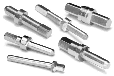
- Shank
Typically considered the upper-body section on a swage pin, this feature is dropped into a mounting hole to perform the swaging/riveting operation. Multiple shank lengths are commonly offered for a single swage pin, varying according to the suggested PCB thickness. A coaxial hole is provided on this feature to allow for the insertion of swage tooling to perform the fastening operation. View Swage Terminal Pins
- Shell
A precision screw machined component, typically cylindrical and manufactured out of a brass alloy. Its primary function is to serve as a housing for the contact clip in female interconnect assemblies such as receptacles or sockets. A prevalent feature in receptacle shells is a drilled hole that is machined through the center; the majority are also designed with a flange used to aid in both receptacle and board assembly. In addition, some shells are designed with unique features for press-fitting, solder tails for through-hole mounting, and various types of wire termination features to allow for use in a wide range of applications.
- Shock
Shock is defined as a motion in which there is a sharp, sudden change in velocity. Excessive shock applied to an electrical connection can result in physical damage to the components, electrical discontinuity, and/or signal loss.
- Shoulder (Flange)
An external rib or lip machined on most pin, receptacle, and spring pin components that is typically the largest external diameter. Most often located on one end of the part but can also be found near the center in certain designs. Its primary function is to assist in board assembly by orienting the product in the mounting hole and providing added support during solder or press-fit mounting. In spring pin and receptacle products, this feature also plays a pivotal role in the assembly of the component.
- Shrink DIP Package

A DIP connector provided on .070" pitch/centers instead of the more common .100” spacing. These packages are useful in applications that require a DIP style connection but cannot afford the board space required for a standard .100” DIP. Learn More

- Shroud
A style of male and female interconnects which uses plastic housings with high walls surrounding the protruding pin array. Once mated, one half of the connector will reside inside the other to create a tight, guided/keyed fit-up and prevent mating error or misalignment. View Examples
- Side Load
A horizontal or lateral force that is applied to a component. Most often referring to spring-loaded products, which involves a sliding/swiping action exerted to the plungers. While a certain degree of lateral/non-vertical engagement is possible for spring pins, excessive side loading can compromise the expected life of the product.
- Single Inline Package (SIP)/Strip
An interconnect component that consists of a rectangular insulator populated with either pins, receptacles, or spring pins. Useful for applications that require mounting multiple discrete interconnect components onto a PCB in a consistent standard pitch. Pitch/pin-to-pin spacing options range from 1mm (.0394”) to 4mm (.1575”), including single, double, and triple row options as well as different termination styles such as through hole, SMT, wire termination and press-fit. View Examples
- Skiving
The displacement of a thin amount of plating material when interconnect components are press-fitted into a mounting hole. While this is a natural byproduct of the assembly operation, soft plating finishes (such as tin) may yield more noticeable amounts. Skiving may also appear when a contact clip is pressed into a receptacle shell; most often with a tin-plated shell and a gold-plated contact combination.
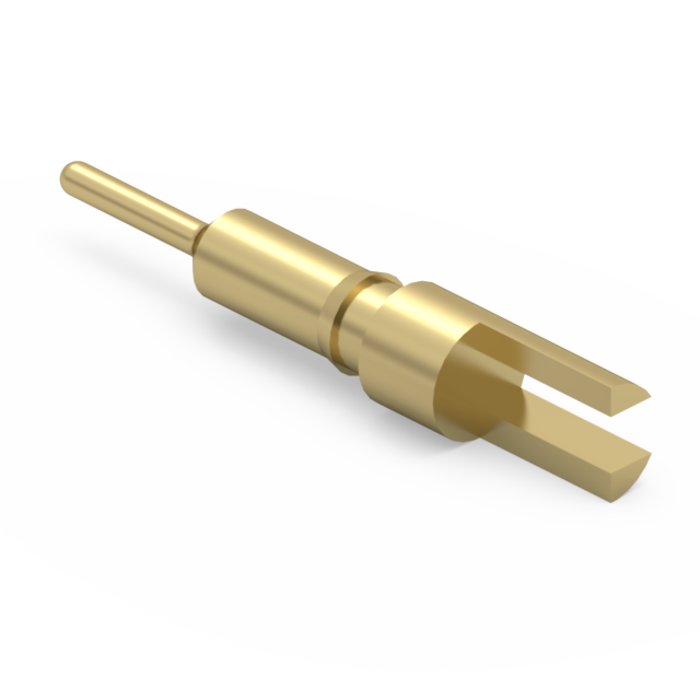
- Slot
A machined feature on an interconnect component in which a section of material is removed from one end by a saw or cutter blade. This feature can be used for a variety of applications including wire termination and alignment purposes. The slot often creates a bifurcated fork at the end of the part, with the opposite end being soldered, swaged or press-fit mounted into the board. View Examples
- Socket
A female interconnect component which is comprised of discrete receptacles assembled into a plastic insulated housing. Intended as the mating half to a suitable male header with appropriate pitch and lead diameters. Offered with various acceptance ranges, grid spacings, position counts and mounting styles; custom designs can also be explored upon request. View Examples
- Solder Tail
- A machined post or lead which protrudes from the bottom of pin, receptacle or spring pin. For through-hole requirements, the tail feature serves as a stable anchor for soldering and mounting purposes.
- Solder Wicking
A problem during a soldering operation where reflowed solder climbs up a lead towards the component and causes reduced solder at the intended joint(s). In open-bottom receptacles, wicking can also lead to solder buildup inside of the component body which may be problematic when inserting a mating lead. Mill-Max's line of organic fibre plug (OFP) receptacles were designed to prevent this by plugging the open bottom with a disposable barrier. View Examples
- Soldercup

A type of wire termination feature that consists of a drilled hole at the end of a pin, receptacle, or spring pin with a radius cutout. This cup feature eases the insertion of the wire and provides better visibility while soldering. Wires as large as 14AWG to as small as 26AWG, and potentially smaller, can be assembled quickly and efficiently. View Examples

- Spring Force
The amount of force required to compress the plunger of a spring pin to a specified distance. This characteristic is primarily driven by the spring component, namely its design and base material. The spring forces specified for Mill-Max spring-loaded products refer to plunger compression at .
- Spring Force Constant
(Conducted on a MM # 0900-X Spring Pin Connector)
k = Force (60) - Preload (25)/Travel (.0275) = 1272.73 g/in.
Preload = 25 g
Force = 60 g
Travel = .0275"
- Spring Rate
The spring rate of a spring will be determined by spring material, diameter of the material, and number of coils per the spring length.
- Standoff / Mounting (Alignment) Peg

A plastic protrusion at the bottom of certain connectors used to raise the product off the PC board to aid in solder fillet formation, board inspection, flux removal, alignment and cleaning. View Example

- Stroke/Travel
- The specified distance by which the plunger of a spring pin compresses when being cycled. Each spring pin is rated for a maximum stroke distance, starting from the product at its initial height in a completely uncompressed state. As a general recommendation, between 25% and 75% of the max. stroke should be used for optimal electrical and mechanical performance. Excessive compression of the plunger past the max. stroke value (over-compression) can jeopardize performance and cause premature failures. Learn More. See operating travel range for more information on stroke/travel.
- Stub Tail
A termination method provided on select DIP, SIP and PGA style sockets. This mounting style is comparable to most standard SMT designs, with the chief exception being the floating nature of the receptacles within the insulator. The added range of movement acts as a buffer and helps compensate for unevenly screened solder paste during assembly. View Examples
- Surface Mount (SMT)
Mounting style in which parts are assembled onto a flat pad/land on the PCB. Mill-Max offers two styles of surface mount features – either a flat bottom base or bent “gull wing” style tails. Surface mount parts are well-suited for automated, high volume builds which use pick & place equipment and controlled soldering processes such as intrusive reflow and pin-in-paste.
In addition to vertical surface mounting, horizontal surface mount (HSMT) parts can be soldered to a pad/land in a parallel fashion for engagement from the side. HSMT parts are also offered in two styles – a flat surface base or bent tails, referred to as “z-bend” tails in the horizontal configuration. View examples
- Swage Mount

A method of mechanically fastening pin terminals to a circuit board, similar in style to riveting. It is commonly used with solder terminals and printed circuit board pins for low to medium volume applications. The swaging technique captures the board between the flared or swaged material and the shoulder of the pin, fastening the pin to the board.
While not formally required, a soldering procedure can be conducted after the swaging process to improve the mechanical and electrical reliability of the connection. Learn More

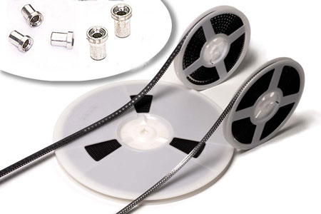
- Tape & Reel
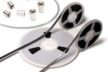
Component packaging suited for use with automated pick & place equipment. Parts are housed on a continuous tape strip, each one placed inside a formed pocket based on the part’s specific design and dimensions. Adjacent pockets are spaced at a consistent distance, referred to as the pocket pitch. The cavities are further secured by a cover tape placed over the top. The entire carrier tape strip is wound up onto a reel for easy loading into a pick & place machine. Learn More
- Target
The mating face for a spring-loaded pin or connector which creates an electrical connection when the plunger is compressed up against it. A target may refer to a land/pad on the PCB, or an additional pin/disc component mounted onto the board or housing. Mill-Max target pins are typically round and gold plated, with either a flat or concave mating surface. Offered in both discrete and connector strip options. View Examples
- Thermal Coefficient of Expansion (TCE)
Expansion of material caused by an increase in temperature.
- Thermoplastics
- Plastic polymers that soften when they are heated and solidify again as they are cooled, allowing for molding/shaping operations such as injection molding. Due to their unique chemical properties, thermoplastic materials can be remolded and recycled without negatively affecting the material’s physical properties. All of Mill-Max’s standard connectors that are assembled with molded plastic insulators/housings would be considered thermoplastics.
- Thermoset
- Plastic polymers that can only be heated and molded once. This makes them ideal for high temperature applications, as excessive and/or prolonged heat will not change or deform the material. Mill-Max utilizes thermoset materials such as FR-4 (G10) in custom machined plastic housings.
- Threading

The defining feature of screws, nuts, and bolts which consist of grooved helical ridges wrapped around a cylinder. Threads are used to mount components onto a board or housing without the use of solder or an adhesive, or for fastening two components together for added mechanical rigidity. A threaded connection requires one component to be machined with exterior threads, allowing it to be torqued into a mating component with corresponding interior threads. The features that support threaded mounting can be found on both discrete and connector-based solutions. View Examples

- Through-Hole Mount (TH)
A termination style provided on both discrete and connector products where a machined tail or post on the bottom of the component is soldered into a mounting hole on a PCB. This termination style is preferred over SMT products in applications where the component may be subjected to lateral loads, since the rigid tail helps anchor the part to the PCB. Mill-Max currently offers through hole termination features in varying lengths and diameters, with options for both vertical and horizontal mounting.
- Tin Whisker Growth
A phenomenon that occurs where small metal hairs grow between soldered joints and/or components, forming mini electrical paths which can lead to short circuits. They pose a serious problem for electronics of all types since they can grow spontaneously, are almost invisible to the naked eye, and can bridge fairly large distances. Whisker growth is most often mitigated by using a combination of tin (Sn) and lead (Pb) where the minimum lead content is 3%. For RoHS compliant applications, specifying a matte finish as opposed to bright finish will also aid in mitigation.
- Top Plate
- The final or topmost plating layer applied to a part which dictates color appearance; Commonly composed of gold, tin/lead or tin. The top plate contributes to performance of the total coating by improving electrical performance, corrosion and wear resistance, and solderability.
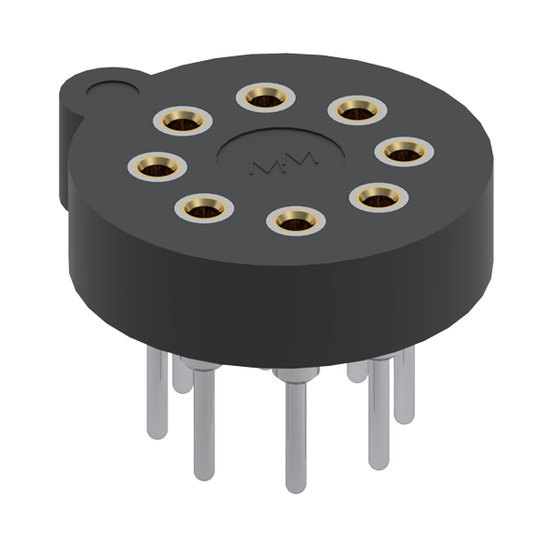
- Transistor Socket (TO)
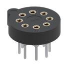
Circular sockets designed to make the insertion/extraction of transistors and diodes easy and convenient, especially in the field. This is achieved by making the device pluggable with a reliable mechanical and electrical connection to the mated transistor lead. The diameters and spacings are pre-determined to meet most standard package types, namely adhering TO-5 and TO-100 footprint requirements. Offered in both through hole and surface mount termination options. View Examples
- Turret

A feature on a pin or receptacle which consists of a post machined with a singular or series of larger diameter heads. The primary purpose of this feature is to facilitate wire termination by providing a surface to wrap and solder a wire to the component. View Examples

- Underplate
The plating layer applied to a part before the top plate or surface coating. This layer is typically composed of either nickel or copper, but other materials can be used as well. The underplate contributes to the performance of the total coating by improving corrosion resistance, wear resistance, and solderability, and by also limiting the potential diffusion of base metal elements into the top plate such as .
- Uniform Orientation/Alignment
In a connector featuring multiple positions of a solder cup pin, receptacle, or spring pin, uniform orientation specifies that each individual cup in a row is aligned toward the same direction. This allows for a simpler, neater soldering process since each row of wires can be assembled from the same side of the connector in an orderly manner.


- Universal Series Bus (USB) Connector
A common type of interface or connector that allows devices to communicate with a host controller such as a personal computer, for data, signal exchange or charging. Examples of peripheral devices typically connected by USB include external hard drives, mice, keyboards, printers, scanners, cameras and other media devices. Mill-Max offers a wide array of USB sockets designed for both SMT and hybrid style mounting. View Examples
- Vacuum Pad
A plastic protrusion featured on select DIP sockets that facilitate pick and place handling. On the larger size sockets, there's also a pad beneath for horizontal transfer. View Examples
- Vent/Vented

A feature on a PCB pin which consists of chamfered cut(s), typically for solder flow and/or to allow gases to escape in a PCB assembly. View Examples
- Vertical Mount
- Components which are intended to be mounted vertically or perpendicular to the board surface. Often provided in different styles, including surface mount, press-fit, and through hole.
- Vibration
- A mechanical phenomenon of oscillations usually observed as a shaking or rattling movement. Minimizing vibration in a system and protecting the system from unwanted vibration are common goals in a mechanical design. Excessive vibration onto a component can cause damage such as wear, signal loss and connector separation.
- Wire Crimp/Termination
An assembly method by which a wire is electrically and mechanically fastened to an interconnect component. This may refer to a soldercup style part, which provides a cut-out for easy access when soldering, or a crimp style part, permitting solder-free crimping into a properly sized barrel. View Examples
- Withdrawal Force
See " Extraction Force"
- Wrapost
A termination style on PCB pins and connectors featuring a post with a square cross section, intended for making electrical connections via wire wrapping. This is a process in which a wire is wrapped around the post to form a gas-tight electrical connection without soldering (when proper tooling is used). Wire wrapping allows for fast repairs as the connection can be removed quickly and easily without damaging the terminal. Mill-Max offers wrapost termination features for a variety of discrete and connector products, often including different length options and # of wraps (commonly 1-3). View Examples
- Wrapost (Terminal or Receptacle)
The length of square cross section of certain pins and receptacles which is used for making electrical connections via wire wrapping. Wire wrapping is a process in which wire is wrapped around the post to form a gas-tight connection without soldering.
- Z-bend
A feature provided on select SIP connectors where two bends are formed into the solder tails of through-hole interconnect components, allowing them to be horizontally surface mounted to the board. This termination method is useful for applications where a horizontal/parallel connection must be made, but the PCB cannot tolerate a right angle through hole component. View Examples
- ZIF
- Zero Insertion Force
- Zinc Migration
A condition that exists when a brass part is plated with tin or gold. The migration of zinc from brass to the plating surface will create a zinc oxide layer which will render the part un-solderable. Zinc migration is prevented by using a copper or nickel as a barrier.