Understanding Mating Pins, Ranges, and Forces
What is the "Range" of a contact clip?
This is the specification of the minimum to maximum pin diameter the contact will accept. The minimum pin diameter inserted into the contact will exhibit the lightest insertion/extraction forces. Conversely, the maximum pin diameter inserted into the contact will exhibit the highest insertion/extraction forces. Inserting the largest possible diameter pin into a contact will effectively form the contact fingers and accelerate its fatigue.
Minimum Pin Insertion Depth
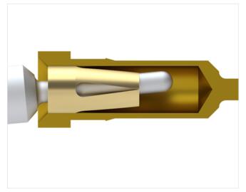
The mated pin should pass a minimum distance, equivalent to the pin diameter, past the end of the contact clip position inside the shell, so the contact fingers can engage and score the mated pin surface.
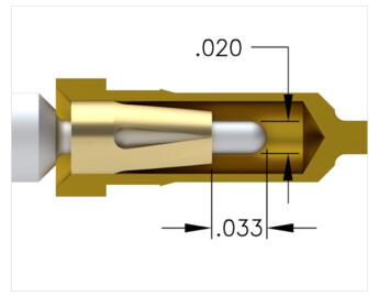
Mating Pin Diameter
Ideally, the Mill-Max contact clip selection should have a pin acceptance mid-range, near the diameter of the mated pin. When designing an interconnect always try to select a Mill-Max contact with a mid-range near your pin diameter. To ensure a reliable electrical and mechanical connection, the mating pin should extend a minimum of one equivalent pin diameter past the end of the contact clip .
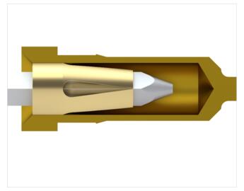
When mating Mill-Max receptacles with square/rectangular shaped leads, we recommend converting the square into a diameter by means of the Pythagorean theorem (a²+b²=c²). This will ensure the pin falls within the receptacle’s acceptance range.
For example, If a square lead is .010”x.020”, it would be calculated as follows:
.010²+.020² = .0005
 .0005” = .022360”
What is the "Compliancy" of a contact clip ?
This is the resultant loss of the lower contact range, due to forming, when a contact clip is engaged by a near maximum range diameter pin. When designing an interconnect, always try to select a Mill-Max contact with a mid-range near your pin diameter.
The Mill-Max "multi-finger" contact exhibits wide compliance, ie: the ability of any single contact to accept a broad range of round pins as well as rectangular or square component leads. This ability is referred to as the contact's "compliancy". The compliancy factor specifies the re-configured operating range after the initial insertion of the largest permissible mating pin. For example: the # 34 contact has an initial operating range from .032" to .047" diameter pins, and a compliancy of .010"; but after insertion of a .047" pin, the contact is sized, and the minimum pin acceptance becomes .047" - .010" = .037". Thus, the new operating range becomes .037" to .047".
For complete specifications on all Mill-Max contact clips, review the General Contact Info in our catalog.
What is the "Initial" Insertion Force / Insertion Force "2nd Cycle"?
The initial insertion force will always be the highest, because the contact plating is in a pristine state. Subsequent insertions will be a slightly lower force.
A note about force graphs
The insertion and extraction force graphs shown for each Mill-Max clip, are a mathematical representation of the average force readings found through testing using a polished bullet nose calibrated pin. These numbers should be used for reference purposes only, and are not intended to represent absolute force values. For customers who need to specify insertion/extraction force parameters on their boilerplate drawings, it is highly recommended they test sample receptacles in a simulation of their anticipated working environment.
Contact clip cycle life
The life cycle of a contact clip is a function of the customer's application. How the clip is engaged / disengaged in the customer's application, will determine how fast or slow the contact fingers fatigue. All metal objects eventually fatigue when exposed to cycling. Fatigue factors include: constant contact cycling (pin insertions) over time, deformation damage of the contact fingers by pin misalignment, and/or forming the contact by inserting a large diameter pin (towards the extreme end of the contact range).
Mill-Max has customers that achieve thousands of cycles out of our contacts by ensuring the mated pin is a diameter within the mid-range of the contact specification, and not rough surfaced or chisel tipped. They ensure the mated pin is engaged/disengaged concentric to the receptacle opening, usually by incorporating alignment guides on both halves of the connector. For customers who need to specify a life cycle parameter on their boilerplate drawings, it is highly recommended they test sample receptacles in a simulation of their anticipated working environment.
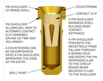
Shell Bulging / Shoulder considerations
Most Mill-Max catalog receptacles incorporate a "shoulder" at the top of the part. This shoulder serves many functions, and is a definite factor affecting the cost of manufacturing non-standard receptacles.
- Automation - Incorporating a pin shoulder on a receptacle design allows Mill-Max to automate contact clip assembly into the shell. This saves us production time and you money.
- Alignment - The shoulder prevents a receptacle from falling through a mounting or plated thru hole and also serves to help keep the pin perpendicular to the circuit board during soldering operations.
- Targeting - Incorporating a pin shoulder allows for a countersink opening providing a larger pin entry to guide the mated pin into the receptacle.
- Strength - If a pin receptacle shell does not have a shoulder, the section of the shell that the contact clip gets press-fit into will slightly bulge anywhere from .001-.003"